
Battery gluing defect detection method and device, electronic equipment and storage medium

A defect detection and gluing technology, which is applied in image data processing, instruments, character and pattern recognition, etc., can solve problems such as cumbersome calculation process, high false detection rate, and no technical solutions, and achieve wide applicability, The effect of high efficiency and high precision

Active Publication Date: 2021-08-27
JIHUA LAB
View PDF6 Cites 3 Cited by
  • Summary
  • Abstract
  • Description
  • Claims
  • Application Information

AI Technical Summary

Problems solved by technology

[0004] Existing glue coating defect detection technology generally adopts image processing combined with manual interpretation. Manual interpretation is relatively subjective and unstable, with a high false detection rate, and the image processing scheme is easily affected by external influences such as ambient light intensity, color, and glue body color. , resulting in unstable detection results
[0005] Therefore, there are schemes on the market that use laser point cloud to process from cross section, but the existing scheme based on laser point cloud to judge from cross section has many redundant judgments and calculations in the judgment process, and it is necessary to obtain height and area through calculation , density and other data, the calculation process is cumbersome
[0006] For the above problems, there is no effective technical solution

Method used


Image

  • Battery gluing defect detection method and device, electronic equipment and storage medium
  • Battery gluing defect detection method and device, electronic equipment and storage medium
  • Battery gluing defect detection method and device, electronic equipment and storage medium

Examples


Embodiment Construction

[0034] The following will clearly and completely describe the technical solutions in the embodiments of the present application with reference to the accompanying drawings in the embodiments of the present application. Obviously, the described embodiments are only some of the embodiments of the present application, not all of them. The components of the embodiments of the application generally described and illustrated in the figures herein may be arranged and designed in a variety of different configurations. Accordingly, the following detailed description of the embodiments of the application provided in the accompanying drawings is not intended to limit the scope of the claimed application, but merely represents selected embodiments of the application. Based on the embodiments of the present application, all other embodiments obtained by those skilled in the art without making creative efforts belong to the scope of protection of the present application.

[0035] It should ...


PUM


Abstract

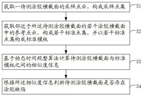
The invention discloses a battery gluing defect detection method and device, electronic equipment and a storage medium, and the method comprises the following steps: obtaining a sampling point cloud of a gluing cross section to be detected, and forming a sampling point set; obtaining reference point clouds in a plurality of gluing cross sections adjacent to the gluing cross section to be tested, forming a plurality of standard point sets, and forming a standard template by the plurality of standard point sets; calculating similarity information between the to-be-tested gluing cross section and the standard template based on a dynamic time warping algorithm; judging whether the gluing cross section to be detected has gluing defects or not according to the similarity information; according to the method, the similarity information of the collection point cloud of the to-be-detected gluing cross section and the reference point cloud of the adjacent gluing cross section is calculated and obtained by using the dynamic time warping algorithm, the existence of the gluing defect is quickly screened and determined according to the similarity information, and the detection method is high in efficiency, high in precision and high in accuracy. The method does not depend on specific forms, numerical values, materials, environments and sample plates for analysis, and has the characteristic of wide application range.

Description

technical field [0001] The present application relates to the technical field of battery detection, and in particular, to a method, device, electronic equipment and storage medium for detecting battery coating defects. Background technique [0002] In battery gluing and testing processes such as mobile phones, battery gluing is an extremely important part of battery production, ensuring accurate and even distribution of adhesives and sealants, which helps to extend the service life of batteries. [0003] Common defects in battery glue coating include: glue overflow, glue holes, and unsaturated glue filling. Timely feedback through glue coating defect detection technology can effectively improve the accuracy of glue coating defect detection and improve the efficiency of inspection quality. [0004] Existing glue coating defect detection technology generally adopts image processing combined with manual interpretation. Manual interpretation is relatively subjective and unstable...

Claims


Application Information

Patent Timeline
Patent Type & Authority Applications(China)
IPC IPC(8): G06T7/00G06K9/32G06K9/62
CPCG06T7/0004G06T2207/10028G06V10/25G06V10/751G06F18/2411G06F18/22
Inventor 张校志林才纺杨远达
Owner JIHUA LAB
Learn More