Five-axis linkage turning plate machining center and application thereof

A five-axis linkage, machining center technology, applied in metal processing equipment, metal processing mechanical parts, manufacturing tools, etc., can solve the problems of inability to achieve five-axis linkage, equipment damage, poor safety, etc., to achieve automatic exchange, convenient grouping. The effect of line use and convenient line grouping

Pending Publication Date: 2021-08-27
沈阳中捷航空航天机床有限公司
View PDF3 Cites 0 Cited by
  • Summary
  • Abstract
  • Description
  • Claims
  • Application Information

AI Technical Summary

Problems solved by technology

[0002] The machining center is a highly automated multifunctional CNC machine tool with a tool magazine and automatic tool changer. The machining center is mainly suitable for processing complex parts such as plates, discs, molds and small shells. The machining center can complete milling , boring, drilling, tapping and other processes, with the continuous development and progress of society, the application of machining centers is becoming more and more extensive. Due to the limitation of head structure and space, the power is suddenly cut off during the operation of the machine tool. At the moment of power failure, the double swing head will suddenly sag due to the action of gravity. The light one will cause equipment damage, and the severe one may cause casualties. , poor security

Method used


Image

  • Five-axis linkage turning plate machining center and application thereof
  • Five-axis linkage turning plate machining center and application thereof
  • Five-axis linkage turning plate machining center and application thereof

Examples


Embodiment Construction

[0029] The following will clearly and completely describe the technical solutions in the embodiments of the present invention with reference to the accompanying drawings in the embodiments of the present invention. Obviously, the described embodiments are only some, not all, embodiments of the present invention. Based on the embodiments of the present invention, all other embodiments obtained by persons of ordinary skill in the art without making creative efforts belong to the protection scope of the present invention.

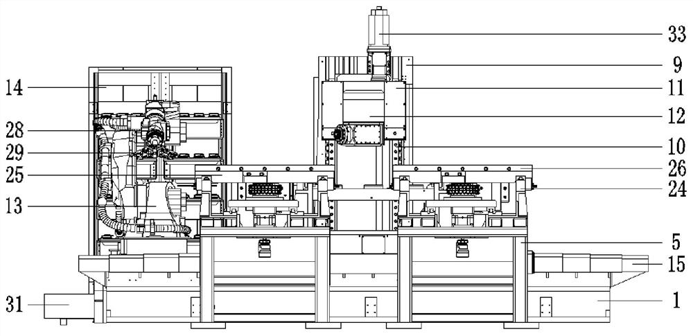
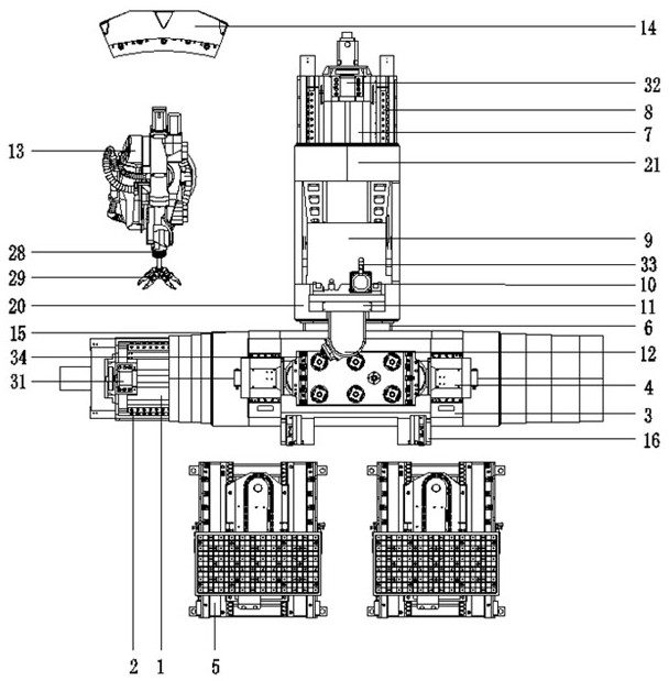
[0030] see Figure 1-6 , a turning plate machining center capable of five-axis linkage, including a horizontal bed 1, a Y-axis drive mechanism 31 is connected to the left end surface of the horizontal bed 1, and a Y-direction slide is fixedly connected to the center of the top of the horizontal bed 1. Rail 2, the upper part of the Y-direction slide rail 2 is movably connected with a swing table support plate 3, and the top of the swing table support plate 3 is...


PUM


Abstract

The invention belongs to the field of horizontal machine tool machining centers, and relates to a five-axis linkage turning plate machining center and application thereof. The five-axis linkage turning plate machining center comprises a transverse lathe bed, a Y-axis driving mechanism is connected to the left side end face of the transverse lathe bed, a Y-direction sliding rail is arranged at the top of the transverse lathe bed, a swing table supporting plate is arranged on the Y-direction sliding rail, and a swing table structure is connected to the top of the swing table supporting plate. A workbench automatic exchange station is arranged on one side of the transverse lathe bed, the other side of the transverse lathe bed is fixedly connected with a longitudinal lathe bed through a connecting support, a Z-direction sliding rail is arranged at the top of the longitudinal lathe bed, a stand column is connected to the Z-direction sliding rail, a Z-axis driving mechanism is arranged on the left side of the stand column and fixedly connected to the upper end face of the longitudinal lathe bed, and an X-direction sliding rail is fixedly connected to the front end face of the stand column. An X-axis driving mechanism is arranged on the upper end face of the stand column, the X-direction sliding rail is movably connected with a spindle box, and the spindle box is fixedly connected with a single swing head. A robot tool changing mechanism and a tool magazine wall assembly are arranged on one side of the longitudinal lathe bed. Five-axis linkage machining is achieved, and potential safety hazards caused by the fact that a machine tool suddenly powers off, and swing heads droop in an existing horizontal machining center are eradicated.

Description

technical field [0001] The invention relates to the technical field of horizontal machining centers, in particular to a turning plate machining center capable of five-axis linkage and its application. Background technique [0002] The machining center is a highly automated multifunctional CNC machine tool with a tool magazine and automatic tool changer. The machining center is mainly suitable for processing complex parts such as plates, discs, molds and small shells. The machining center can complete milling , boring, drilling, tapping and other processes, with the continuous development and progress of society, the application of machining centers is becoming more and more extensive. Due to the limitation of head structure and space, the power is suddenly cut off during the operation of the machine tool. At the moment of power failure, the double swing head will suddenly sag due to the action of gravity. The light one will cause equipment damage, and the severe one may caus...

Claims


Application Information

Patent Timeline
Patent Type & Authority Applications(China)
IPC IPC(8): B23Q1/01B23Q1/66B23Q3/155
CPCB23Q1/015B23Q1/66B23Q3/155
Inventor 高长才刘峰刘丽英马俊杰姜楠林青高崇牛石从邓长安王明智李树鹏陈晨季柏树沈会王淼
Owner 沈阳中捷航空航天机床有限公司
Why Eureka
Try Eureka