
Device and method for realizing position calibration based on binocular vision measurement and high-precision positioning fusion technology

A technology of binocular vision measurement and binocular vision system, which is applied in measuring devices, radio wave measurement systems, satellite radio beacon positioning systems, etc., can solve problems such as high labor costs, slow construction progress, and high risk of labor operations. Achieve the effects of improving operation efficiency, reducing operation risk, and low-cost surveying and mapping

Pending Publication Date: 2021-08-24
易通共享技术(广州)有限公司
View PDF0 Cites 3 Cited by
  • Summary
  • Abstract
  • Description
  • Claims
  • Application Information

AI Technical Summary

Problems solved by technology

During the operation, the construction personnel need to hold the measurement antenna and the antenna feeder, and place the measurement antenna on the road marking line on the site to measure the coordinate information. The construction personnel need to keep moving to measure, especially the subject three site, which shares social Vehicle roads, one road is 3km long, two-way and multi-lane, and an average operation requires 2 people for more than 2 days. The current situation of site surveying and mapping is high labor costs, slow construction progress, and high risk of labor operations.

Method used


Image

  • Device and method for realizing position calibration based on binocular vision measurement and high-precision positioning fusion technology
  • Device and method for realizing position calibration based on binocular vision measurement and high-precision positioning fusion technology
  • Device and method for realizing position calibration based on binocular vision measurement and high-precision positioning fusion technology

Examples


Embodiment Construction

[0037] The present invention will be further described below in combination with specific embodiments. Among them, the accompanying drawings are only for illustrative purposes, and what are shown are only schematic diagrams or simple schematic diagrams, rather than actual pictures, and should not be understood as limitations on this patent; in order to better illustrate the embodiments of the present invention, some parts of the accompanying drawings will be Omissions, enlargement or reduction do not represent the size of the actual product; for those skilled in the art, it is understandable that some well-known structures and their descriptions in the drawings may be omitted.

[0038] In the drawings of the embodiments of the present invention, the same or similar symbols correspond to the same or similar components; , "vertical", "horizontal" and other indicated orientations or positional relationships are based on the orientations or positional relationships shown in the dr...


PUM


Abstract

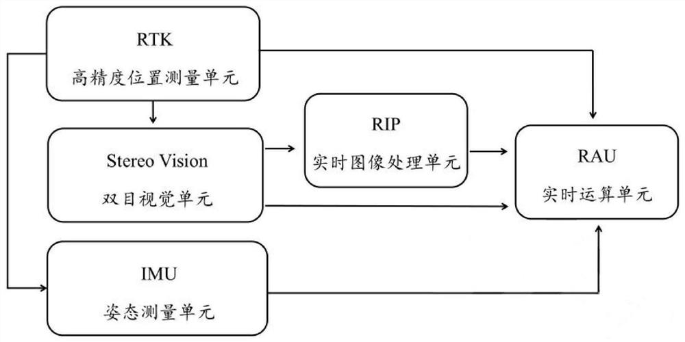
The invention relates to the technical field of road surveying and mapping, in particular to a device and a method for realizing position calibration based on a binocular vision measurement and high-precision positioning fusion technology, which utilize an RTK high-precision positioning technology to acquire geodetic coordinate position information and binocular parallax in real time to acquire the relative position of a measured object, and in combination with attitude information assistance, the high-precision geodetic coordinate position information of the lane line or the ground marker line is fused and solved in real time, so that high-precision, low-cost and high-efficiency surveying and mapping of the driving school site are realized.

Description

technical field [0001] The invention relates to the technical field of road surveying and mapping, in particular to a device and method for realizing position calibration based on binocular vision measurement and high-precision positioning fusion technology. Background technique [0002] In 2012, the Ministry of Public Security formulated the new "Regulations on the Application and Use of Motor Vehicle Driver's License". The introduction of high-precision GNSS positioning in the driving test system can realize the field test and the actual road test. With the comprehensive promotion of high-precision GNSS positioning in the driving school business, the demand for high-precision site surveying and mapping has arisen as the times require. At present, the construction of site surveying and mapping projects still relies on traditional manual surveying and mapping, which has the characteristics of high labor costs, slow construction progress, and high risk of labor operations. ...

Claims


Application Information

Patent Timeline
Patent Type & Authority Applications(China)
IPC IPC(8): G01S19/41G01S19/49
CPCG01S19/41G01S19/49
Inventor 房华刘水红舒征峰
Owner 易通共享技术(广州)有限公司
Learn More