Unmanned helicopter equipment compartment

A technology for unmanned helicopters and equipment cabins, applied in the field of equipment cabins, can solve the problems of low manufacturing cost, increased load mounting space, and weight of equipment cabins, and achieve the goals of reducing surface treatment costs, increasing space utilization, and reducing structural weight Effect

Active Publication Date: 2022-05-13
南京航天国器智能装备有限公司
View PDF6 Cites 0 Cited by
  • Summary
  • Abstract
  • Description
  • Claims
  • Application Information

AI Technical Summary

Problems solved by technology

However, the traditional equipment cabin is arranged in the front section of the fuselage and is made of pure glass fiber reinforced plastic, which has a low manufacturing cost. However, the density of fiberglass fiber reinforced plastic itself is relatively high, so the overall equipment cabin is relatively heavy, and fiberglass fiber reinforced plastic does not have the ability to conduct electricity. If it encounters a thunderstorm, lightning strikes may occur event
At the same time, the existing equipment cabin does not have the function of electromagnetic shielding, and the space utilization rate is not high, and the overall center of gravity of the UAV is behind, so it is necessary to counterweight in the equipment cabin to keep the overall center of gravity of the aircraft at the position of the main axis.
Moreover, the traditional engine radiator is generally arranged under the fuselage frame. The advantage is that it can increase the stability of the aircraft, but it also takes up the space for the aircraft to increase the load mounting.

Method used


Image

  • Unmanned helicopter equipment compartment
  • Unmanned helicopter equipment compartment
  • Unmanned helicopter equipment compartment

Examples


Embodiment Construction

[0021] The technical solution of the present invention will be further described below in conjunction with the accompanying drawings.

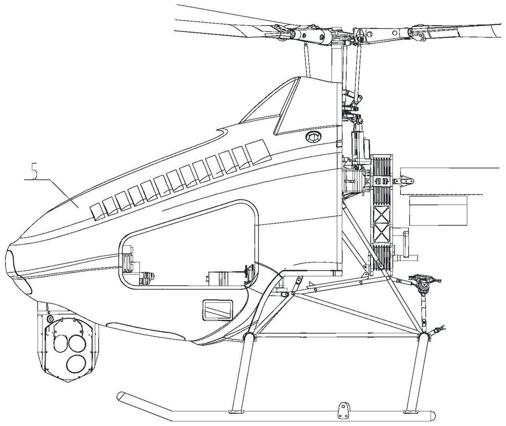
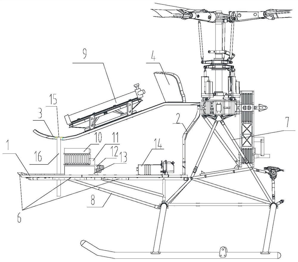
[0022] Such as figure 1 and figure 2 As shown, a kind of unmanned helicopter equipment cabin of the present invention comprises equipment cabin floor 1, equipment cabin rear partition 2, radiator lower partition 3, radiator rear partition 4, equipment cabin outer cover 5, equipment cabin support plate 6 and Floor support assembly 8. The rear bulkhead 2 of the equipment compartment is vertically arranged at the rear end of the floor 1 of the equipment compartment. The lower bulkhead 3 of the radiator is positioned above the rear bulkhead 2 of the equipment compartment. The lower bulkhead 3 of the radiator is used to place the radiator 9. The partition 3 includes arc-shaped plates, inclined plates and straight plates arranged in sequence. The radiator rear bulkhead 4 is located above the straight plate of the radiator lower bulkhead. The ou...


PUM


Abstract

The invention discloses an unmanned helicopter equipment cabin, which comprises an equipment cabin floor, a vertical equipment cabin rear partition, a radiator lower partition located above the equipment cabin rear partition for placing a radiator, and a radiator lower partition. The radiator rear bulkhead above the plate and the equipment compartment outer cover that forms the inner cavity of the equipment compartment with the radiator rear bulkhead, the radiator lower bulkhead, the equipment compartment floor and the equipment compartment rear bulkhead, wherein the equipment compartment outer cover is supported by the equipment compartment The board is connected to the floor of the equipment compartment, and a floor support assembly is connected between the floor of the equipment compartment and the rack. The invention divides the equipment cabin into upper and lower layers as a whole, which are separated by the lower partition of the radiator. The radiator is installed on the upper layer, and the avionics equipment, power supply equipment and flight control device are installed on the lower layer. The counterweight is discarded to increase the space utilization rate.

Description

technical field [0001] The invention relates to an equipment cabin, in particular to an unmanned helicopter equipment cabin. Background technique [0002] Large-scale unmanned helicopters have the advantages of relatively low cost, no risk of casualties, good maneuverability, and convenient use. They have been widely used in forest fire prevention, border patrol, emergency disaster relief, drug control, anti-terrorism, and police investigation. However, the traditional equipment cabin is arranged in the front section of the fuselage and is made of pure glass fiber reinforced plastic, which has a low manufacturing cost. However, the density of fiberglass fiber reinforced plastic itself is relatively high, so the overall equipment cabin is relatively heavy, and fiberglass fiber reinforced plastic does not have the ability to conduct electricity. If it encounters a thunderstorm, lightning strikes may occur event. At the same time, the existing equipment cabin does not have the...

Claims


Application Information

Patent Timeline
Patent Type & Authority Patents(China)
IPC IPC(8): B64C1/22B64C27/06
CPCB64C1/22B64C27/06B64U10/10B64U2101/00
Inventor 杨维顺贾支鹏李涛迟鹏汤为伟潘道亿
Owner 南京航天国器智能装备有限公司
Why Eureka
Try Eureka