
Power battery isolation placement box

A power battery and placing box technology, applied in the direction of secondary batteries, battery pack components, circuits, etc., can solve the problems of difficult dissipation of battery heat, easy burnout and damage of lines, and difficult disassembly of the isolation box, so as to facilitate maintenance and repair. The effect of ensuring the operating environment and facilitating installation and disassembly

Inactive Publication Date: 2021-08-20
徐雄飞
View PDF0 Cites 0 Cited by
  • Summary
  • Abstract
  • Description
  • Claims
  • Application Information

AI Technical Summary

Problems solved by technology

[0003] However, the existing isolation box completely isolates the power battery, which not only makes it difficult to dissipate the heat energy inside the battery, but also accumulates a large amount of heat energy in the isolation box, causing the internal circuit to be easily burned out and damaged. The isolation box fixed by bolts is in the process of maintenance It is also difficult to disassemble, and it is not convenient for professionals to overhaul, so a power battery isolation storage box is proposed to solve the above-mentioned problems

Method used


Image

  • Power battery isolation placement box
  • Power battery isolation placement box
  • Power battery isolation placement box

Examples


Embodiment 1

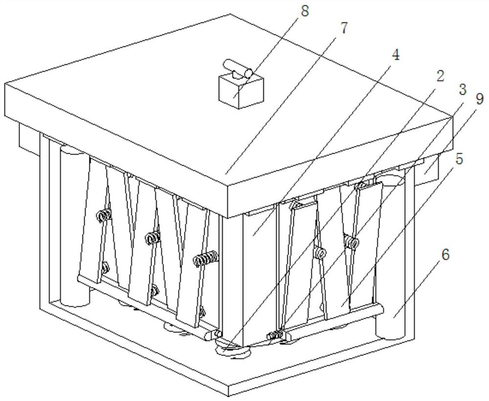
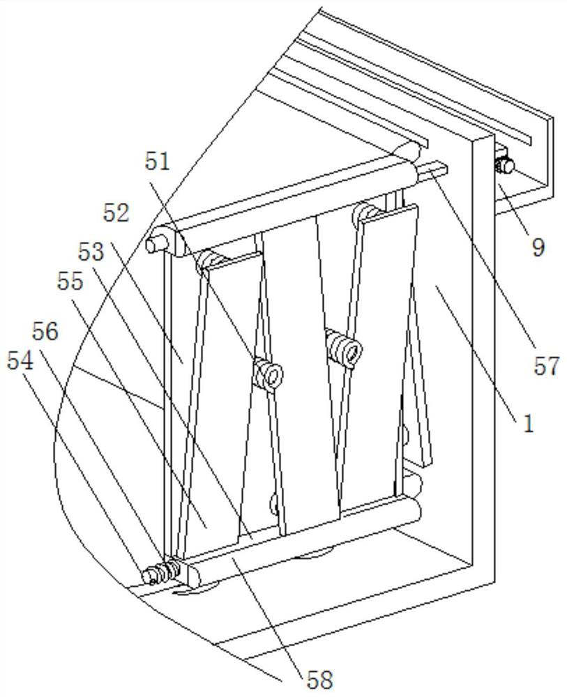
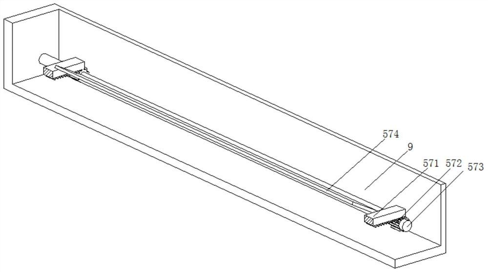
[0031] An isolated storage box for a power battery, such as Figure 1-Figure 5 As shown, it includes a box body 1, the bottom of the box body 1 is welded with a buffer spring 2, the top of the buffer spring 2 is welded with a bottom plate 3, the top of the bottom plate 3 is movably connected to a battery body 4, and the surface of the battery body 4 is provided with a buffer cooling mechanism 5. The inside of the box body 1 is fixedly connected with the protective side column 6, the top of the box body 1 is clamped with a top cover 7, the inside of the top cover 7 is provided with a snap-in mechanism 8, and the surface of the box body 1 is welded with a side box 9, The bottom of the top cover 7 is provided with a buffer plate.

[0032] After the top cover 7 is clipped and fixed with the box body 1, the buffer plate at the bottom contacts with the top of the battery body 4, and shock-absorbing protection is performed on the bottom, and the buffer spring 2, the bottom plate 3 an...

Embodiment 2

[0044] Such as Figure 6-7 As shown, on the basis of Embodiment 1, in this embodiment, the clamping mechanism 8 includes a sliding seat 81 and a starting device 85, the surface of the sliding seat 81 is slidably connected with the inner wall of the top cover 7, and the bottom of the sliding seat 81 is welded Folding block 82 is arranged, and the internal screw thread of slide seat 81 is connected with threaded rod 83, and the left end of threaded rod 83 is welded with bevel gear-84, and the surface of threaded rod 83 is connected with the interior of top cover 7 by rotation, and folded block 82 The surface of the surface is slidably connected with the inner wall of the top cover 7.

[0045] By setting the clamping mechanism 8, the interaction between the various internal structures can be used to achieve the effect of easy installation and disassembly of the box body 1 as a whole, and at the same time, the internal self-locking function can be used to stably fix the box body 1...


PUM


Abstract

The invention relates to the technical field of power batteries, and discloses a power battery isolation placement box which comprises a box body. Buffer springs are welded to the bottom of the box body, a bottom plate is welded to the tops of the buffer springs, a battery body is movably connected to the top of the bottom plate, and a buffer cooling mechanism is arranged on the surface of the battery body. Protective side columns are fixedly connected to the interior of the box body, a top cover is clamped to the top of the box body, a clamping mechanism is arranged in the top cover, and a side box is welded to the surface of the box body. According to the power battery isolation placement box, the buffer cooling mechanism and the clamping mechanism are arranged, and mutual operation of all structures in the isolation placement box is utilized, so that shock absorption protection is performed while the box body isolates a battery body, and the effect of performing air cooling on the interior of the box body while shock absorption protection is performed is achieved; and meanwhile, the box body is convenient to mount and dismount, so that the effect of conveniently overhauling and maintaining the battery body is achieved.

Description

technical field [0001] The invention relates to the technical field of power batteries, in particular to an isolated storage box for power batteries. Background technique [0002] The power battery is the power supply that provides the power source for the tool. It mostly refers to the battery that provides power for electric vehicles, electric trains, electric bicycles, and golf carts. Lead-acid batteries, open-type tubular lead-acid batteries and lithium iron phosphate batteries are mainly used to provide electric energy for the starting and ignition of the engine and the use of on-board electronic equipment. In order to avoid leakage and other phenomena, an external power battery is usually installed. Isolation box. [0003] However, the existing isolation box completely isolates the power battery, which not only makes it difficult to dissipate the heat energy inside the battery, but also accumulates a large amount of heat energy in the isolation box, causing the interna...

Claims


Application Information

Patent Timeline
Patent Type & Authority Applications(China)
IPC IPC(8): H01M50/242H01M50/244H01M50/249H01M10/613H01M10/625H01M10/6563H01M10/6554
CPCH01M10/613H01M10/625H01M10/6554H01M10/6563Y02E60/10
Inventor 不公告发明人
Owner 徐雄飞
Learn More