Axial flow pump impeller locking device

A locking device and axial-flow pump technology, which is applied to the components, pumps, and pump elements of the pumping device for elastic fluids, and can solve the problems of easy breakage of bolts and easy loosening of nuts.

Pending Publication Date: 2021-08-20
XIANGYANG WU ER WU PUMP IND
View PDF0 Cites 0 Cited by
  • Summary
  • Abstract
  • Description
  • Claims
  • Application Information

AI Technical Summary

Problems solved by technology

[0004] The purpose of the present invention is to provide an axial flow pump impeller locking device to solve the problems that the bolts are easy to break and the nuts are easy to loosen in the prior art.

Method used


Image

  • Axial flow pump impeller locking device
  • Axial flow pump impeller locking device

Examples


Embodiment

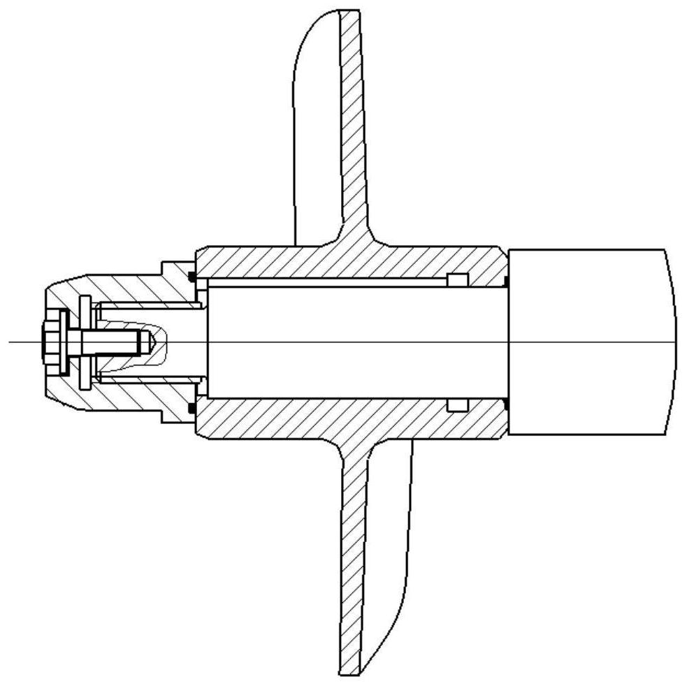
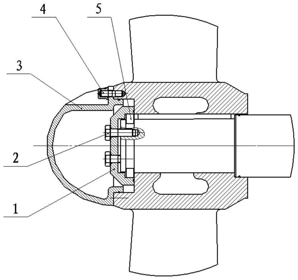
[0022] Such as figure 2 As shown, an axial flow pump impeller locking device of the present invention includes a locking cover 1, a snap ring 5 and a locking bolt 2;

[0023] On the front end face of the pump shaft, there are two circumferentially evenly distributed threaded holes in the axial direction, and an annular positioning groove is opened on the front side wall of the pump shaft;

[0024] The cover body of the lock cover 1 is provided with a bolt passage hole corresponding to the threaded hole on the front end of the pump shaft, and the inner wall of the mouth of the lock cover 1 is provided with an annular limiting groove;

[0025] The clasp 5 is an annular assembly enclosed by two parts. The inner diameter and height of the clasp 5 are matched with the diameter and width of the annular positioning groove on the side wall of the front end of the pump shaft. The outer diameter of the 5-piece matches the diameter of the annular limiting groove on the inner wall of th...


PUM


Abstract

The invention discloses an axial flow pump impeller locking device. The axial flow pump impeller locking device comprises a locking cover, a clamping ring and locking bolts; two or more threaded holes evenly distributed in the circumference are axially formed in the front end face of a pump shaft; an annular positioning groove is formed in the side wall of the front end of the pump shaft; bolt passing holes corresponding to the threaded holes in the front end face of the pump shaft are formed in a cover body of the locking cover; an annular limiting groove is formed in the inner wall of an opening of the locking cover; the clamping ring is an annular combined piece defined by two sub-pieces; after an impeller and the pump shaft are assembled, the clamping ring is sleeved with the annular positioning groove of the pump shaft, and the outer ring of the rear end face of the clamping ring combined piece is tightly attached to the front end face of an impeller hub; the front end of the pump shaft is sleeved with the locking cover, and the locking cover is fixed through the locking bolts; and the locking cover enables the two sub-pieces of the clamping ring to be limited in the radial direction through the annular limiting groove in the inner wall of the opening of the locking cover. The impeller locking device can reliably lock the impeller on the pump shaft.

Description

technical field [0001] The invention relates to an axial flow pump impeller locking device, which belongs to the technical field of mechanical transmission. Background technique [0002] Axial flow pump is a centrifugal pump with large flow and low head, widely used in farmland irrigation, municipal water supply and drainage, water diversion projects, power plant circulating water projects, nuclear power, water jet propulsion, phosphoric acid industry, etc. The performance characteristics of the axial flow pump are different from that of the general centrifugal pump. Its performance curve is saddle-shaped, and there are many extreme values. It will generate a large impact load during the start and stop stages, and the impeller locking structure will bear a large force during this process. Therefore, in the design of the impeller locking device, impact resistance and anti-loosening are the key points. [0003] In existing technologies, such as figure 1 As shown, the structu...

Claims


Application Information

Patent Timeline
IPC IPC(8): F04D29/20
CPCF04D29/20
Inventor 王小锋李家虎万仁伟李新宋寅刘稳杰刘黎明
Owner XIANGYANG WU ER WU PUMP IND
Why Eureka
Try Eureka