
Spindle-shaped air entraining structure for secondary air system of gas turbine

A technology of secondary air and gas turbines, which is applied to the components of pumping devices for elastic fluids, liquid fuel engines, mechanical equipment, etc., and can solve the problems of large bleed air resistance, insufficient strength and vibration performance, and complex structure of ordinary bleed air, etc. problems, to achieve the effects of smooth streamlines, shortened axial space, and improved operational safety

Active Publication Date: 2021-08-17
XI AN JIAOTONG UNIV
View PDF10 Cites 0 Cited by
  • Summary
  • Abstract
  • Description
  • Claims
  • Application Information

AI Technical Summary

Problems solved by technology

[0003] The purpose of the present invention is to provide a spindle-shaped bleed air structure for the secondary air system of a gas turbine to solve the problems of large bleed air resistance of a gas turbine, complex structure of an ordinary bleed air, and insufficient strength and vibration performance at high speeds

Method used


Image

  • Spindle-shaped air entraining structure for secondary air system of gas turbine
  • Spindle-shaped air entraining structure for secondary air system of gas turbine
  • Spindle-shaped air entraining structure for secondary air system of gas turbine

Examples


Embodiment Construction

[0036] The present invention will be further described in detail below in conjunction with the accompanying drawings. However, it should not be understood that the scope of the above-mentioned subject matter of the present invention is limited only to the following content. Without departing from the above idea of ​​the present invention, various replacements or changes made according to common technical knowledge and customary means in this field shall be included in the scope of the present invention.

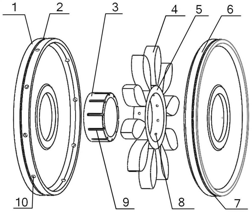
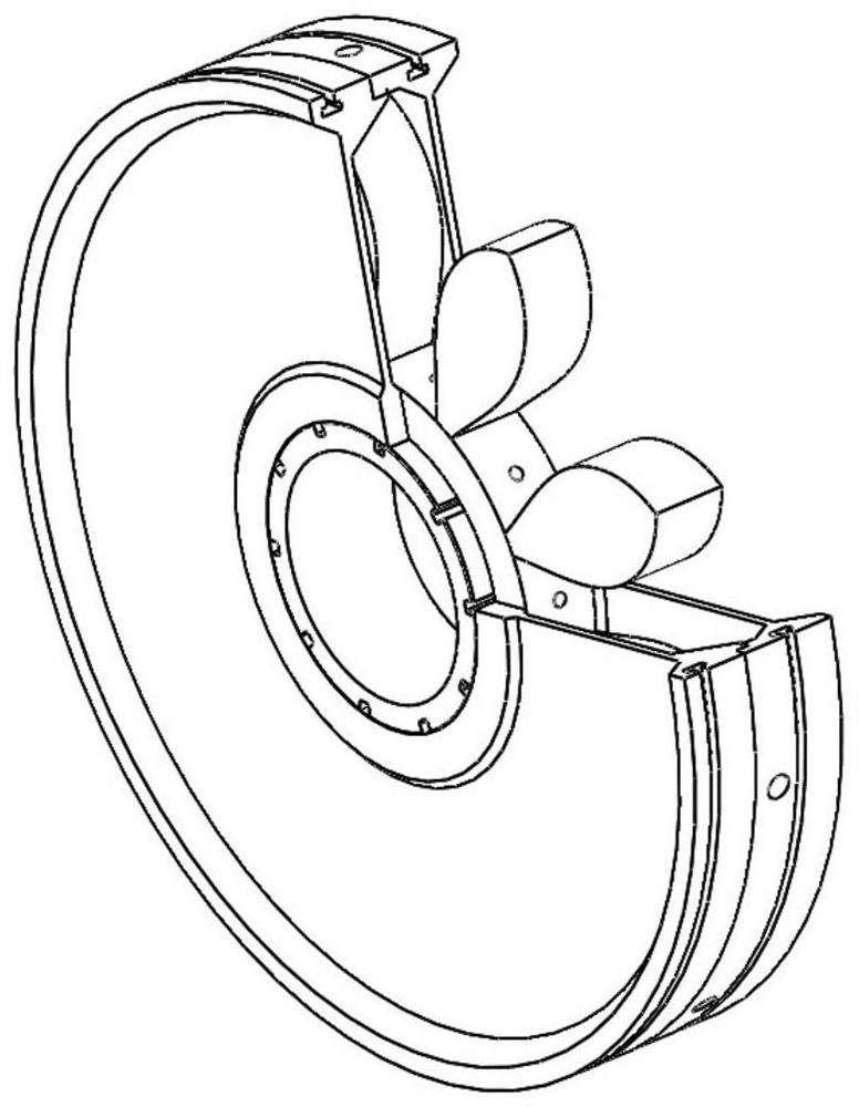
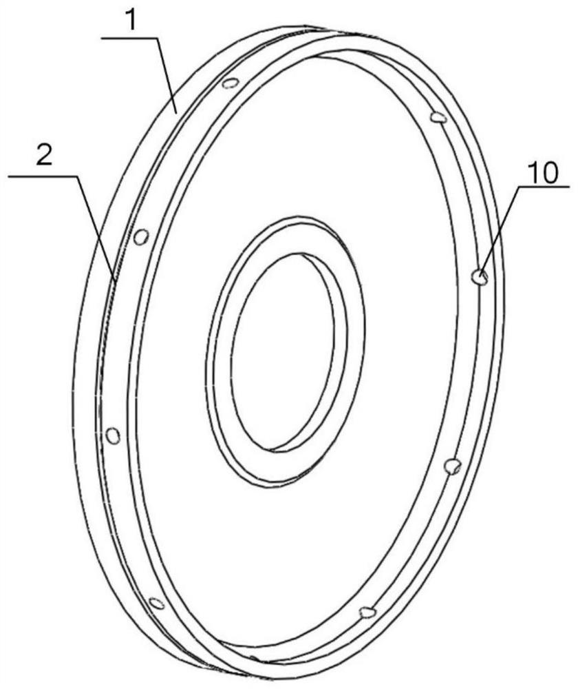
[0037] see Figure 1 to Figure 6 , a spindle-shaped air-inducing structure for a gas turbine secondary air system provided by the present invention includes a first-stage rotor disc 1 , a spindle-shaped air-inducing structure, an air-inducing disc and a second-stage rotor disc 7 . The first-stage rotor wheel disc 1 is engraved with the first-stage rotor wheel groove 2, and 8-12 air-introduction holes 10 are evenly opened along the circumferential direction, and the hole diam...


PUM

PropertyMeasurementUnit
Apertureaaaaaaaaaa
Apertureaaaaaaaaaa

Abstract

The invention discloses a spindle-shaped air entraining structure for a secondary air system of a gas turbine. The spindle-shaped air entraining structure comprises a two-stage rotor wheel disc, a spindle-shaped air entraining structure body and an air entraining disc. The two-stage rotor wheel disc and the spindle-shaped air entraining structure body are arranged on the air entraining disc in a sleeved mode, an air inlet hole on the rotor wheel disc right faces the tip end of the spindle-shaped air entraining block, and an air entraining hole on the spindle-shaped air entraining structure body right faces an air entraining groove on the air entraining disc. During working, mainstream fluid enters a disc cavity area through the air inlet hole on a first-stage rotor wheel disc in the radial direction. The air flow in a disc cavity is guided by a spindle-shaped air guiding block and passes through the disc cavity area through a gradually-shrinking-gradually-expanding channel. Afterwards, the airflow enters air outlet holes on a fixed disc in the radial direction, and the air outlet holes directly face air the entraining groove on the air entraining disc. the airflow turns in the air entraining groove in the flowing direction and is led out in the axial direction. The air entraining structure body is suitable for different working conditions by selecting reasonable structure parameters. The spindle-shaped air entraining structure for the secondary air system of gas turbine provided by the invention has the advantages of high efficiency, low resistance, compact structure, suitability for high rotating speed and the like, and has wide market prospect.

Description

technical field [0001] The invention relates to a spindle-shaped air-introduction structure used in the secondary air system of the gas turbine, which is used for reducing the vortex of the disc cavity between stages of the gas turbine. Background technique [0002] For the gas turbine cycle, increasing the inlet temperature of the turbine can improve the operating efficiency and power of the stage, but it also leads to high thermal stress on the hot end parts of the turbine, which often exceeds the temperature range that the material can withstand. High-efficiency cooling technology The research is in urgent need of development, and for now, film cooling is one of the most effective cooling methods for gas turbines. The low-temperature gas required for film cooling generally passes through the bleed air device arranged between the discs, and is extracted from the front end component, that is, the main flow of the compressor. The pressure of the mainstream working fluid of ...

Claims


Application Information

Patent Timeline
IPC IPC(8): F04D29/26F04D29/66
CPCF04D29/26F04D29/666F04D29/667Y02T50/60
Inventor 谢永慧李良梁刘玉鹏张荻
Owner XI AN JIAOTONG UNIV
Learn More