
Stable type correcting groove for sliding door

A technology for rectifying grooves and sliding doors, which is applied to the layout of windows/doors, door/window accessories, and wing leaves. It can solve problems such as damage to rectifying groove components, collision noise of sliding doors, and left and right swaying of rectifying grooves. The effect of protecting the pulley and avoiding damage due to excessive collision

Pending Publication Date: 2021-08-17
闫晓军
View PDF3 Cites 0 Cited by
  • Summary
  • Abstract
  • Description
  • Claims
  • Application Information

AI Technical Summary

Problems solved by technology

[0003] For the sliding of the sliding door, it mainly achieves the effect through the sliding movement between the rectifying groove assembly and the slide rail. The existing rectifying groove assembly is generally composed of a circular shaft wheel, which slides in the slide rail groove with a fixed width. However, when manufacturing slide rails, the width between the inner walls of the channels is slightly larger than the width of the correction groove. When the correction groove is artificially pushed and pulled, the correction groove will sway left and right, which will cause the sliding door to swing greatly. phenomenon, and the left and right swing of the correction groove will collide with the inner wall of the slide rail, causing collision noise when the sliding door moves, and also causing damage to the correction groove components

Method used


Image

  • Stable type correcting groove for sliding door
  • Stable type correcting groove for sliding door
  • Stable type correcting groove for sliding door

Examples


Embodiment Construction

[0019] The following will clearly and completely describe the technical solutions in the embodiments of the present invention with reference to the accompanying drawings in the embodiments of the present invention. Obviously, the described embodiments are only some, not all, embodiments of the present invention. Based on the embodiments of the present invention, all other embodiments obtained by persons of ordinary skill in the art without making creative efforts belong to the protection scope of the present invention.

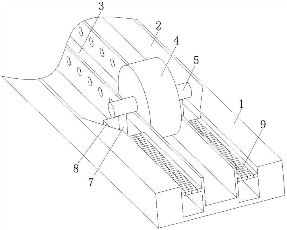
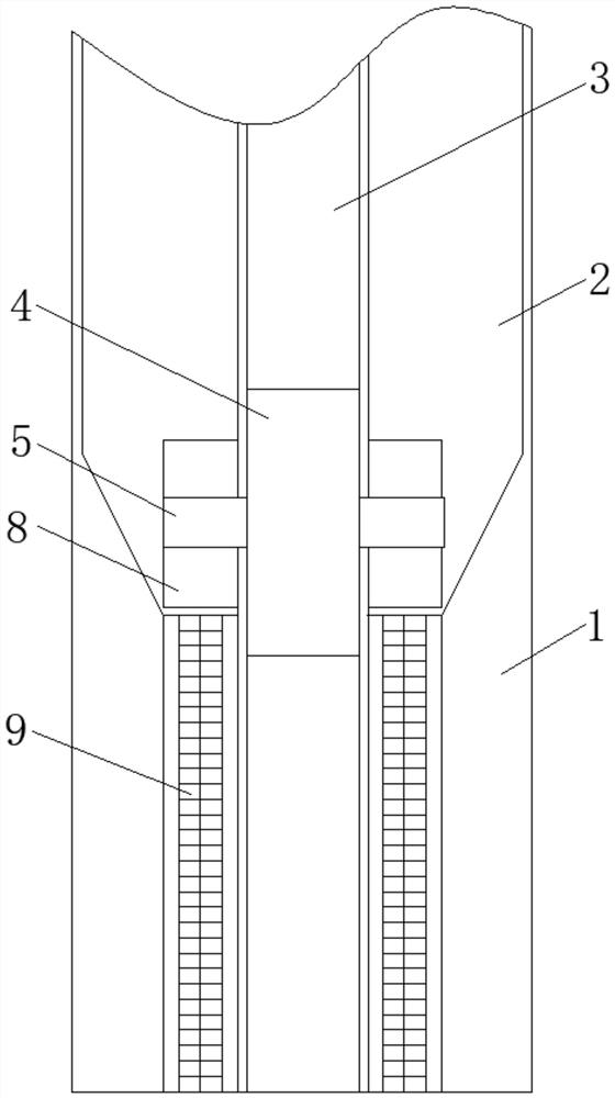
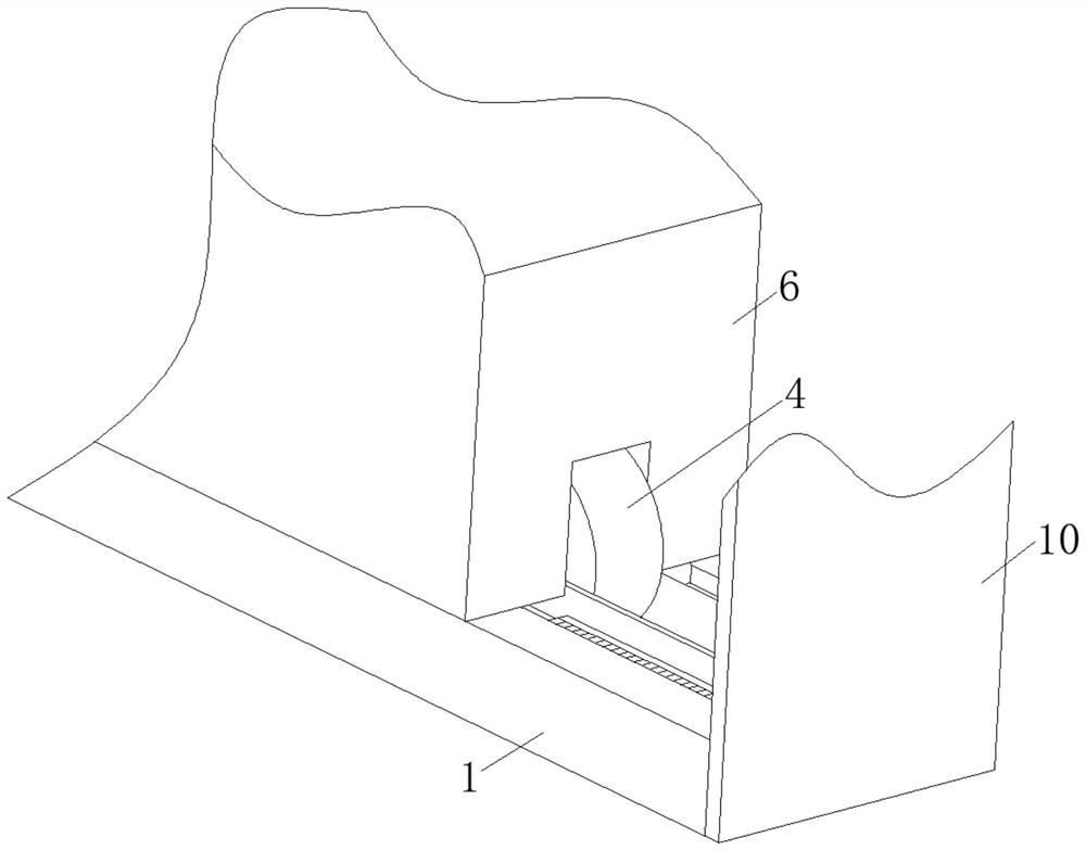
[0020] see Figure 1-4 , a stable correction groove for a sliding door, including a slide rail 1, two correction grooves 2 are provided on both sides of the slide rail 1, a slide groove 3 is provided in the middle of the slide rail 1, and pulleys are movable inside the slide groove 3 4. The center shaft 5 is fixedly installed in the middle of the pulley 4, and the door panels 6 are movably installed on both sides of the center shaft 5. When the door panel 6 of...


PUM


Abstract

The invention relates to the technical field of furniture equipment, and discloses a stable type correcting groove for a sliding door. The stable type correcting groove comprises a sliding rail door frame, wherein two correcting groove door frames are arranged on the two sides of the sliding rail door frame, a sliding groove door frame is arranged in the middle of the sliding rail door frame, and a pulley door frame is movably arranged in the sliding groove door frame. Through holes are formed in the two sides of a sliding groove, the sliding moving speed of a pulley in the sliding groove is used for promoting the pressure difference to be generated in the correcting groove and the sliding groove in the two sides of the sliding rail, the correcting groove and the sliding groove are promoted to be kept stable, the phenomenon that the pulley shakes, and consequently the sliding door swings greatly is avoided, through the correcting groove in the specific shape, a compression sliding block is used for moving forwards, air flow in the correcting groove is compressed, the sliding speed of the pulley is promoted to start to be reduced, and therefore speed reduction and stopping of the pulley are achieved, and the problems that due to the fact that the sliding speed of the pulley is too high, a door plate collides with the door frame, the door plate is damaged, and springback is caused are solved.

Description

technical field [0001] The invention relates to the technical field of furniture equipment, in particular to a stable straightening groove for a sliding door. Background technique [0002] A sliding door is a family door that can be pushed and pulled at will. It is mainly composed of upper sliding rails, lower rails, pulleys, and correction groove components. It is mainly used in living rooms, exhibition halls, bookcases, etc. [0003] For the sliding of the sliding door, it mainly achieves the effect through the sliding movement between the rectifying groove assembly and the slide rail. The existing rectifying groove assembly is generally composed of a circular shaft wheel, which slides in the slide rail groove with a fixed width. However, when manufacturing slide rails, the width between the inner walls of the channels is slightly larger than the width of the correction groove. When the correction groove is artificially pushed and pulled, the correction groove will sway le...

Claims


Application Information

Patent Timeline
Patent Type & Authority Applications(China)
IPC IPC(8): E05D15/06E05D13/00E06B3/46
CPCE05D15/066E05D13/00E06B3/4636
Inventor 闫晓军
Owner 闫晓军
Learn More