Screw feeder for steel preparation

A screw feeder, steel technology, applied in conveyor objects, cleaning devices, loading/unloading, etc., can solve the problems of reduced output, smaller pitch of screw blades, slowed output speed of screw feeder, etc. The effect of slowing down the output speed and preventing it from flying out

Pending Publication Date: 2021-08-17
许雯雯
View PDF10 Cites 1 Cited by
  • Summary
  • Abstract
  • Description
  • Claims
  • Application Information

AI Technical Summary

Problems solved by technology

[0003] But there are following deficiencies in the prior art: a kind of screw feeder that is used for steel preparation at present, owing to be that iron ore and the carbon of right amount ratio are mixed and transported, so that the coal with humidity can stick when spiral blade rotates. Sticking to the surface of the blade and inside the output pipe body, the distance between the screw blades with sticky carbon blocks becomes smaller under continuous rotation, which in turn causes the output speed of the screw feeder to slow down and the output volume to decrease

Method used


Image

  • Screw feeder for steel preparation
  • Screw feeder for steel preparation
  • Screw feeder for steel preparation

Examples


Embodiment 1

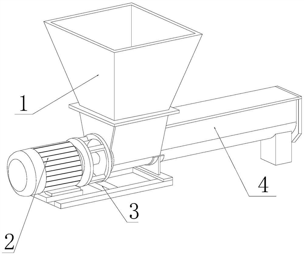
[0030] as attached figure 1 to attach Figure 5 Shown:

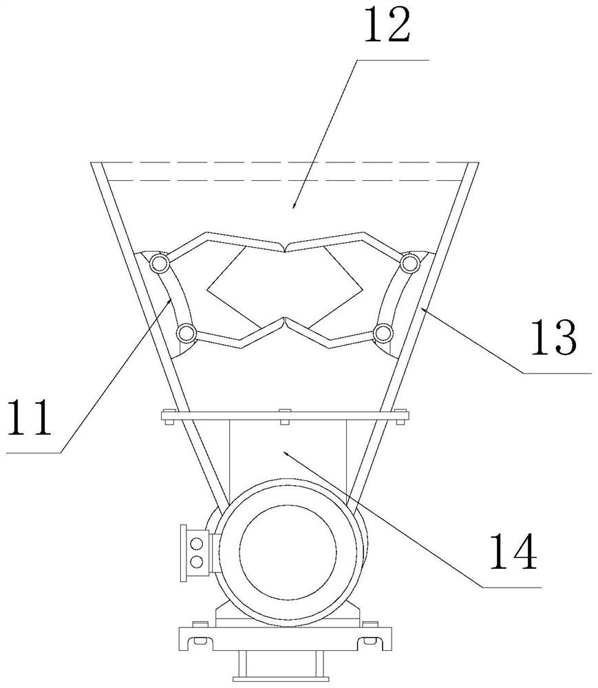
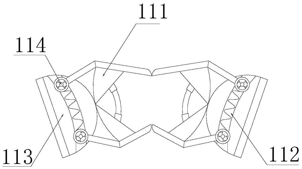
[0031] Its structure includes a lower hopper 1, a driving machine 2, a support platform 3, and a conveying pipe 4. The lower end of the lower hopper 1 is welded to the top of the surface of the conveying pipe 4, and the top of the conveying pipe 4 is fixed to the surface of the driving machine 2 by bolts. The lower end of the driving machine 2 is embedded and connected with the surface of the support platform 3, and the upper end of the support platform 3 is integrally matched with the lower hopper 1. The lower hopper 1 includes a dust-proof baffle 11, a movable cavity 12, an inner hopper wall 13, and a feeding mouth 14, the end of the dust-proof baffle 11 is embedded and connected with the surface of the inner bucket wall 13, the inner side of the inner bucket wall 13 is movably matched with the inside of the movable chamber 12, and the lower end of the movable chamber 12 is in clearance fit with the top end of the mat...

Embodiment 2

[0038] as attached Figure 6 to attach Figure 9 Shown:

[0039] Wherein, the conveying pipe 4 includes a spiral blade 41, a discharge port 42, a conveying cavity wall 43, and a driving rotating rod 44. end and the inner wall of the conveying chamber wall 43 in a clearance fit, the lower surface of the top end of the conveying chamber wall 43 is integrally embedded and connected with the discharge port 42, the surface of the spiral blade 41 is movably matched with the surface of the conveying chamber wall 43, and the center of the spiral blade 41 It is embedded and connected with the surface of the driving rotating rod 44, and its surface is in active cooperation with the surface of the conveying chamber wall 43. Among them, the spiral blade 41 is beneficial to cooperate with the transportation of steel raw materials, and the driving rotating rod 44 drives it to rotate as a whole to reach the top. After that, it is discharged from the discharge port 42.

[0040] Wherein, th...


PUM


Abstract

The invention discloses a screw feeder for steel preparation. The screw feeder structurally comprises a discharging hopper, a driving machine, a supporting table and a conveying pipe, wherein the lower end of the discharging hopper is welded to the top end of the surface of the conveying pipe, the top end of the conveying pipe is fixed to the surface of the driving machine through bolts, the lower end of the driving machine is fixedly connected to the surface of the supporting table in an embedded manner, and the upper end of the supporting table is in overall clearance fit with the discharging hopper; and the discharging hopper comprises a dustproof baffle, a movable cavity, an inner hopper wall and a feeding port. According to the screw feeder, a spiral blade is driven by a driving rotating rod, scraping plates slide in clamping grooves fixedly embedded in the surface of a block body through rotating centrifugal force, the scraping plates are matched with the surface of an external sliding rail to slide, coal adhering to the surface of the block body is vibrated and shaken off through sliding of the block body, and then the wall of an inner cavity is scraped through scraping strips under throwing-out of centrifugal force, so that the coal adhering to the wall of the inner cavity is effectively scraped, and the problems that the output speed of the spiral feeder is reduced and the output quantity is reduced due to coal assistance of the wall of the inner cavity are solved.

Description

technical field [0001] The invention relates to the technical field of steel preparation, in particular to a screw feeder for steel preparation. Background technique [0002] The screw feeder drives the internal screw screw to rotate through the motor to push the internal materials to achieve the purpose of conveying. It can carry out material conveying horizontally, inclined or vertically. It is necessary to transport and mix steel raw materials. Steel is made of iron ore as raw material, adding an appropriate amount of carbon, and sometimes adding some other substances to make steel for different purposes; [0003] But there are following deficiencies in the prior art: a kind of screw feeder that is used for steel preparation at present, owing to be that iron ore and the carbon of right amount ratio are mixed and transported, so that the coal with humidity can stick when spiral blade rotates. Sticking to the surface of the blade and inside the output pipe body, the distan...

Claims


Application Information

Patent Timeline
IPC IPC(8): B65G33/24B65G65/46B65G69/18B65G33/26B65G45/14
CPCB65G33/24B65G65/46B65G69/181B65G33/265B65G45/14
Inventor 许雯雯
Owner 许雯雯
Why Eureka
Try Eureka