
Vibration motor and electronic equipment

A vibration motor and vibration component technology, which is applied to reciprocating/oscillating/vibrating magnetic circuit components, electrical components, electromechanical devices, etc., can solve problems such as weak vibration, small frequency bandwidth, and small vibration amplitude of vibration motors

Pending Publication Date: 2021-08-13
VIVO MOBILE COMM CO LTD
View PDF0 Cites 0 Cited by
  • Summary
  • Abstract
  • Description
  • Claims
  • Application Information

AI Technical Summary

Problems solved by technology

Current vibrating motors usually provide shock sensation by means of reciprocating motion of mass blocks connected with springs. However, limited by the structural components of this vibrating motor, only when the power supply frequency matches the corresponding parameters of the vibrating motor, can the vibrating motor Only when the power supply frequency is not within the aforementioned range, the vibration amplitude of the vibration motor is small and the vibration feeling is weak. Therefore, the frequency bandwidth of the current vibration motor is relatively small.

Method used


Image

  • Vibration motor and electronic equipment
  • Vibration motor and electronic equipment
  • Vibration motor and electronic equipment

Examples


Embodiment Construction

[0028] The technical solutions in the embodiments of the present application will be clearly and completely described below in conjunction with the drawings in the embodiments of the present application. Apparently, the described embodiments are part of the embodiments of the present application, not all of them. Based on the embodiments in this application, all other embodiments obtained by persons of ordinary skill in the art without creative efforts fall within the protection scope of this application.

[0029] The terms "first", "second" and the like in the specification and claims of the present application are used to distinguish similar objects, and are not used to describe a specific sequence or sequence. It should be understood that the terms so used are interchangeable under appropriate circumstances such that the embodiments of the application can be practiced in sequences other than those illustrated or described herein, and that references to "first," "second," etc...


PUM


Abstract

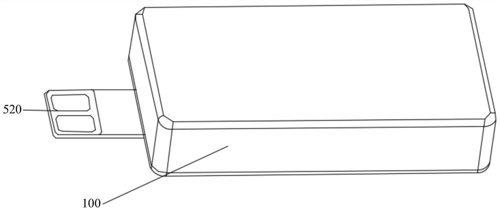
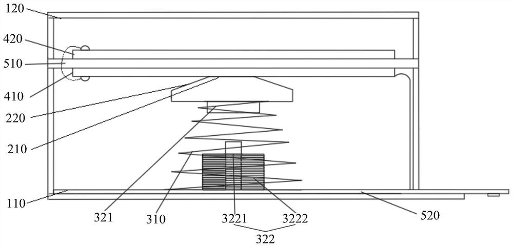
The invention discloses a vibration motor and electronic equipment, and belongs to the field of communication equipment. The vibration motor comprises a shell, a mass block, a deformation part matched with the mass block, a first vibration assembly and a second vibration assembly. The two opposite ends of the deformation part are fixed to the shell, and the deformation part is located between a first surface and a second surface which are oppositely arranged in the shell. The first vibration assembly comprises a driving part which is installed on the shell and matched with the mass block. The second vibration assembly comprises a first piezoelectric structural part attached to the surface of the deformation part. Under the condition that the driving part is power on, the driving part drives the mass block to do reciprocating motion between the first surface and the second surface; and under the condition that the first piezoelectric structural part is powered on, the first piezoelectric structural part generates bending deformation and drives the deformation part to deform so as to drive the mass block to reciprocate between the first surface and the second surface. According to the technical scheme, the problem that the frequency band width of an existing vibration motor is relatively small can be solved.

Description

technical field [0001] The application belongs to the technical field of communication equipment, and in particular relates to a vibration motor and electronic equipment. Background technique [0002] With the development of technology, more and more technologies are applied to electronic devices. For example, in order to improve the dustproof and waterproof performance of the electronic device, the physical buttons in the electronic device can be replaced with virtual buttons, and a vibration motor can be configured so that when the virtual button is pressed, it can still have the pressing vibration of the physical button. Current vibrating motors usually provide shock sensation by means of reciprocating motion of mass blocks connected with springs. However, limited by the structural components of this vibrating motor, only when the power supply frequency matches the corresponding parameters of the vibrating motor, can the vibrating motor Only when a larger amplitude can b...

Claims


Application Information

Patent Timeline
IPC IPC(8): H02N2/00H02K1/34H02K33/02H02K33/04
CPCH02N2/0015H02N2/005H02K1/34H02K33/02H02K33/04
Inventor 陈旭蔡程
Owner VIVO MOBILE COMM CO LTD
Learn More