A reinforcement and anti-vibration device for a substation battery
A technology of anti-shock device and storage battery, which is applied in the direction of battery pack parts, circuits, electrical components, etc., can solve the problems that cannot be popularized and applied in a large area, and achieve the effects of ensuring safety, convenient replacement and maintenance, and improving charging and discharging efficiency
- Summary
- Abstract
- Description
- Claims
- Application Information
AI Technical Summary
Problems solved by technology
Method used
Image
Examples
Embodiment 1
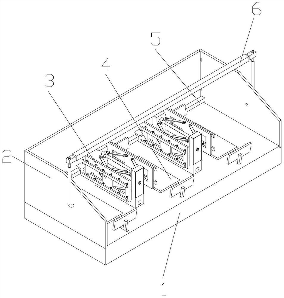
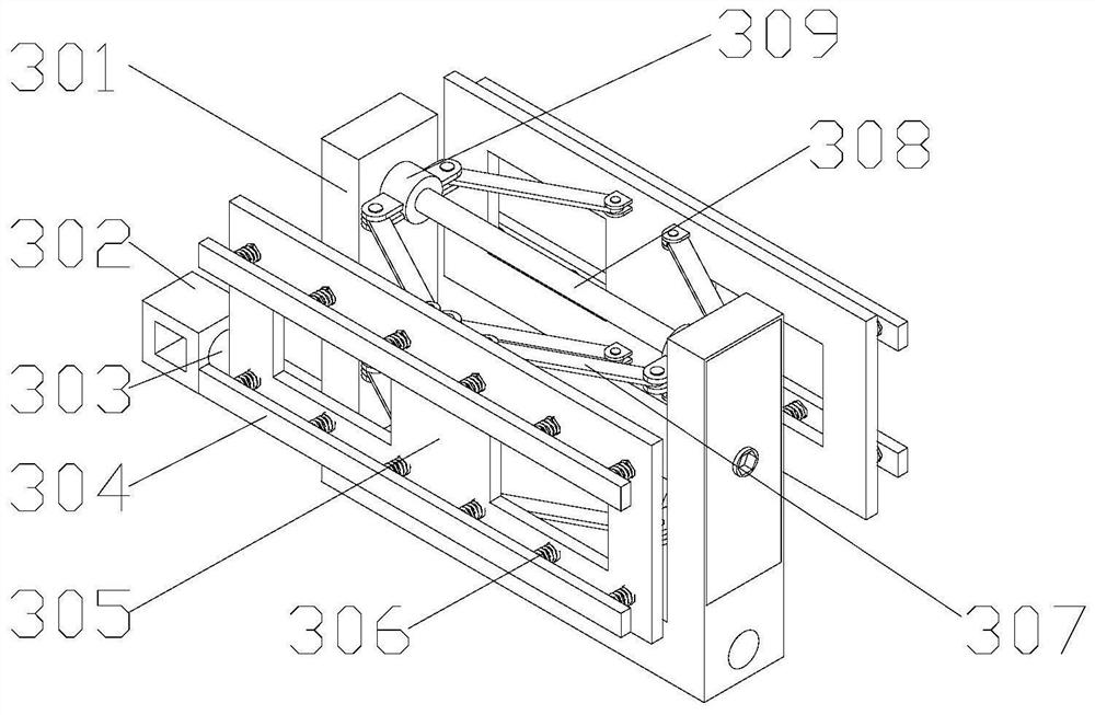
[0032] A reinforcement and anti-vibration device for a battery in a substation, comprising a base 1, on which a mounting frame 2 and a vibration-damping mechanism 4 are mounted, the base 1 adopts a hollow structure, and a sliding rod 5 is installed on the mounting frame 2, and the sliding rod 5 A fastening mechanism 3 is installed on it, and the vibration damping mechanism 4 is intersected with the fastening mechanism 3. A mounting base 7 is installed on the bottom of the base 1. The vibration damping mechanism 4 includes a splint 401, a rotating rod 403, and a rotating shaft 402. , a placement plate 408, a first sleeve 405, a first spring 407, a connecting rod 404 and a fixed rod 406, the fixed rod 406 is installed on the bottom plate in the cavity of the base 1, and the first sleeve 405 is sleeved on On the fixed rod 406, the top of the first sleeve 405 extends through the base 1 to the top of the base 1, the first spring 407 is sleeved under the first sleeve 405 on the fixed...
Embodiment 2
[0039] The difference from Embodiment 1 is that there are two threaded rods 308, and the two threaded rods 308 are installed on the fastening frame 301 one by one, and the two threaded rods 308 are arranged to ensure that the support plate 305 and the clamping The stability of the plate 304 when moving ensures the clamping quality.
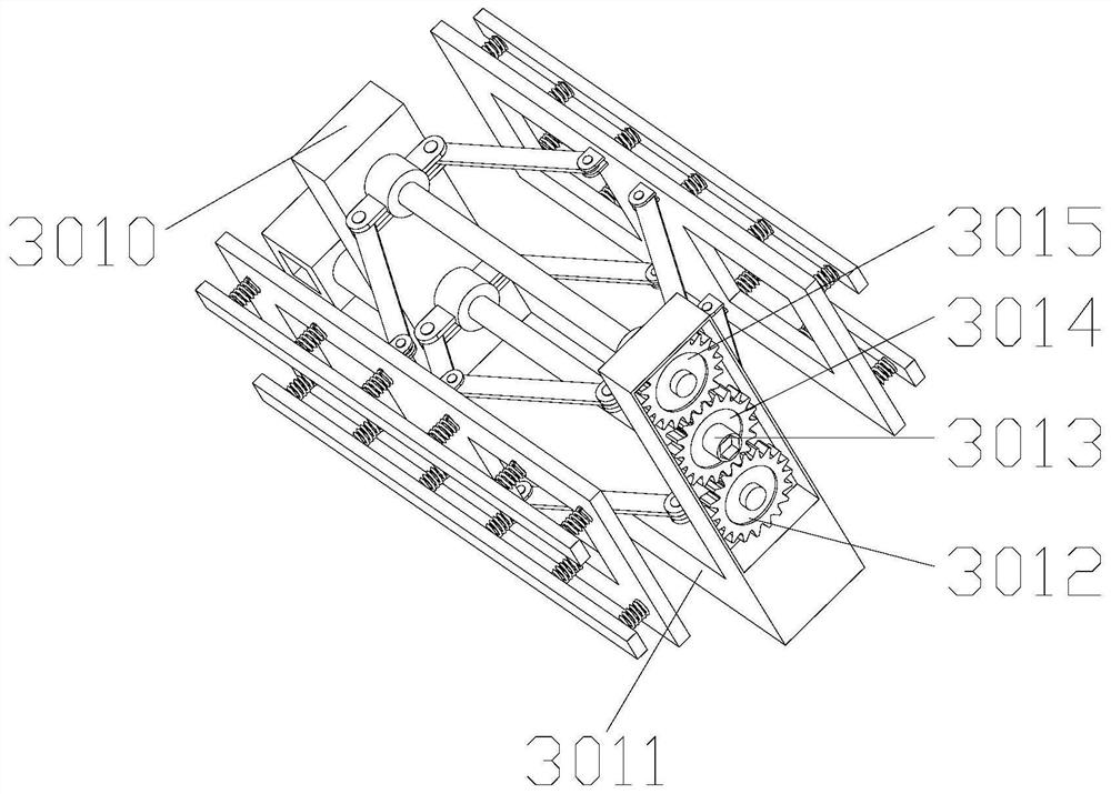
[0040] The fastening frame 301 includes a support horizontal plate 3011 and support vertical bars 3010 installed at both ends of the support horizontal plate 3011, and one of the support vertical bars 3010 is a hollow structure, and a first gear 3012 is installed inside the support vertical bar 3010 , a fixed shaft 3013, a second gear 3014, and a third gear 3015, the first gear 3012 and the third gear 3015 are installed on two threaded rods 308 respectively, the fixed shaft 3013 is installed on a support vertical bar 3010, and One end of the fixed shaft 3013 runs through the support vertical bar 3010 and extends to the outside of the support verti...
Embodiment 3
[0043] The difference from Embodiment 1 and Embodiment 2 is that a clamping device 6 is also installed on the mounting frame 2, and the clamping device 6 includes a third connecting rod 603, a fourth connecting rod 601, a connecting piece 604, The rotating shaft 605, the limiting rod 606 and the third spring 602, the rotating shaft 605 is symmetrically installed on both ends of the limiting rod 606, the connecting piece 604 is installed on the rotating shaft 605, and one end of the third connecting rod 603 is installed on On the connector 604, the fourth connecting rod 601 adopts an L-shaped structure, and a groove is opened on the upper part of the fourth connecting rod 601, and the lower part of the fourth connecting rod 601 is rotatably installed on the side plate of the mounting frame 2, and the third connecting rod 601 The other end of the rod 603 is arranged in the groove, and the third spring 602 is arranged in the groove, and one end of the third spring 602 is installed...
PUM
 Abstract
Description
Claims
Application Information
 - Generate Ideas
- Intellectual Property
- Life Sciences
- Materials
- Tech Scout
- Unparalleled Data Quality
- Higher Quality Content
- 60% Fewer Hallucinations
Browse by: Latest US Patents, China's latest patents, Technical Efficacy Thesaurus, Application Domain, Technology Topic, Popular Technical Reports.
© 2025 PatSnap. All rights reserved.Legal|Privacy policy|Modern Slavery Act Transparency Statement|Sitemap|About US| Contact US: help@patsnap.com


