
Software-defined method of software-defined equipment and software-defined equipment

A software-defined and software-defined platform technology, applied in the field of data transmission, can solve problems that do not involve the reconstruction of functional modules, and do not propose the overall architecture of the software-defined module system system

Active Publication Date: 2021-11-05
湖南博匠信息科技有限公司
View PDF5 Cites 0 Cited by
  • Summary
  • Abstract
  • Description
  • Claims
  • Application Information

AI Technical Summary

Problems solved by technology

[0005] The main purpose of the present invention is to provide a software-defined method for software-defined equipment, which aims to solve the problem that the existing technology does not propose the overall architecture of the software-defined module system system, nor does it involve the functional module reconstruction under the overall architecture of the software-defined module system system way problem

Method used


Image

  • Software-defined method of software-defined equipment and software-defined equipment
  • Software-defined method of software-defined equipment and software-defined equipment
  • Software-defined method of software-defined equipment and software-defined equipment

Examples


no. 1 example to no. 3 example

[0073] see image 3 and Figure 5 , based on the first to third embodiments of the software-defined method for software-defined equipment of the present invention, in the fourth embodiment of the software-defined method for software-defined equipment of the present invention, the business function unit is connected with the When the software defines the debugging interface area of ​​the platform management controller signal connection; the software-defined method of the software-defined equipment also includes the following steps:

[0074] Step S30, obtaining debugging instructions and debugging data;

[0075] Step S40, according to the debugging instruction, send a control flow from the chassis management controller to the software-defined platform management controller of the corresponding basic function module through the bus-type network, and send a control flow from the chassis management controller to the corresponding basic function module through the SERDES bus. The ...

no. 1 example to no. 4 example

[0091] Based on the first to fourth embodiments of the software-defined method for software-defined equipment of the present invention, the fifth embodiment of the software-defined method for software-defined equipment of the present invention further includes:

[0092] Step S70, when the start signal of the service function unit is detected, verify through the software-defined platform management controller;

[0093] Step S80, after the verification is passed, the running program is sent to the business function unit, so that the business function unit starts.

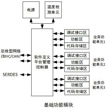
[0094] Specifically, in each basic function module, at least one of a debugging interface area, a function area, and a code storage area is serially connected between the business function unit and the software-defined platform management controller. In this embodiment, at least a code storage area is serially connected between the service function unit and the software-defined platform management controller. When th...

no. 1 example to no. 5

[0096] Based on the first to fifth embodiments of the software-defined method for software-defined equipment of the present invention, in the sixth embodiment of the software-defined method for software-defined equipment of the present invention, the chassis management controller sends each of the base The data information sent by the function module includes a time synchronization code; the software-defined method of the software-defined equipment also includes:

[0097] Step S90, each of the basic function modules receives the data information sent by the chassis management controller;

[0098] Step S100, each of the basic function modules corrects the local time according to the time synchronization code in the data information, so as to keep the time of each of the basic function modules synchronized.

[0099] Specifically, the software-defined equipment of the present invention can also be provided with a clock synchronization interface, and the clock synchronization inte...


PUM


Abstract

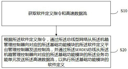
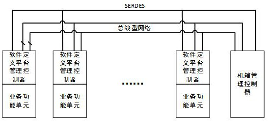
The invention discloses a software-defined method for software-defined equipment and software-defined equipment. The equipment includes a basic function module and an intelligent out-of-band management module; the basic function module includes a software-defined platform management controller and a business function unit; the intelligent out-of-band management module Including a chassis management controller; the method includes: according to a software-defined instruction, sending a control flow and a key low-speed data flow from the chassis management controller to the software-defined platform management controller of the basic function module through a bus-type network, and from the chassis management through a SERDES bus The controller sends high-speed data streams, debugging data streams and time synchronization data streams to the corresponding service function units of the basic function modules, so as to execute the software definition of the basic function modules. The technical solution of the present invention aims to solve the problem that the prior art does not propose the overall architecture of the software-defined module system system, nor does it involve the reconfiguration method of the functional modules under the overall architecture of the software-defined module system system.

Description

technical field [0001] The present invention relates to the technical field of data transmission, in particular to a software-defined method for software-defined equipment and a software-defined equipment. Background technique [0002] At present, the research and development process of equipment often only stipulates indicators such as external form, functional performance, and environmental adaptability, without paying attention to the technical system and system architecture of the specific realization. Different technical teams may design products with completely different architectures based on the same technical requirements, resulting in end users obtaining many products with similar functions from different technical teams, but these product parts with duplicate functions cannot be replaced with each other. When similar products are needed, the technical team needs to redesign each functional module again. In the 1990s, the U.S. Department of Defense proposed the co...

Claims


Application Information

Patent Timeline
Patent Type & Authority Patents(China)
IPC IPC(8): G06F13/42H04J3/06H04L12/40H04L12/24
CPCG06F13/4282G06F2213/0002H04J3/0638H04L12/40H04L41/0631
Inventor 谢启友
Owner 湖南博匠信息科技有限公司
Learn More