


Quick Research
Generate reliable direction feasibility study reports for your R&D in just a few steps.

Technical Q&A
Discover and master advanced knowledge NOW. Basics, ideas, possibilities, all at once.

Find Solutions
As an expert in R&D theories, this can generate solutions to your technical problems instantly.

Evaluate Feasibility
Analyze your overall solution with one click, know your potential R&D risks in advance.

Monitor Landscape
Get weekly tech updates, stay abreast of the latest tech innovations and key insights.
Anti-outrush device for expressway toll station
A technology of high-speed toll stations and anti-scouring devices, which is applied to roads, restricted traffic, roads, etc., can solve the problems of poor interception and anti-scouring effects, and achieve excellent use effects, good anti-scourage effects, and improved anti-scouring effects
- Summary
- Abstract
- Description
- Claims
- Application Information
AI Technical Summary
Problems solved by technology
Method used
Image

Examples
Embodiment 1
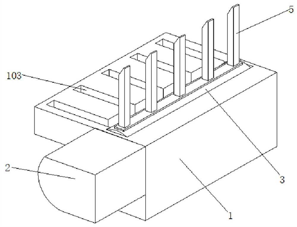
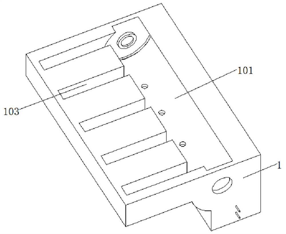
[0039] Embodiment 1 discloses an anti-shock device for high-speed toll stations, refer to the attached figure 1 , attached figure 2 , attached image 3 And attached Figure 4 , its main body includes a pre-embedded box 1, a drum chamber 101 is opened inside the pre-buried box 1, and a drive transmission box 2 is provided on one end of the pre-embedded box 1. In the drum cavity 101, a cylindrical drum 3 is rotated, and the upper surface of the cylindrical drum 3 is fixedly connected with a group of vertically arranged vertical gear rods 5. When setting, the vertical gear rods 5 arranged on the cylindrical drum 3 do not Less than four, and the distance between every adjacent two vertical bars 5 is no more than 50cm.
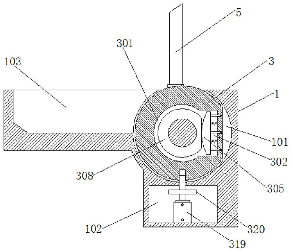
[0040] A cylindrical inner chamber 301 is provided inside the cylindrical drum 3 , and a bar-shaped groove 302 is provided at the right end of the cylindrical inner chamber 301 , and a plane 303 is provided on the outer surface of the cylindrical drum 3 on one ...
Embodiment 2
[0044] Embodiment 2 discloses an improved anti-shock device for high-speed toll stations based on Implementation 1. Refer to the attached figure 1 , attached figure 2 , attached image 3 And attached Figure 4 , its main body includes a pre-embedded box 1, a drum chamber 101 is opened inside the pre-buried box 1, and a drive transmission box 2 is provided on one end of the pre-embedded box 1. In the drum cavity 101, a cylindrical drum 3 is rotated, and the upper surface of the cylindrical drum 3 is fixedly connected with a group of vertically arranged vertical gear rods 5. When setting, the vertical gear rods 5 arranged on the cylindrical drum 3 do not Less than four, and the distance between every adjacent two vertical bars 5 is no more than 50cm.
[0045] A cylindrical inner chamber 301 is provided inside the cylindrical drum 3 , and a bar-shaped groove 302 is provided at the right end of the cylindrical inner chamber 301 , and a plane 303 is provided on the outer surfac...
PUM
 Abstract
Description
Claims
Application Information
 - R&D Engineer
- R&D Manager
- IP Professional
- Industry Leading Data Capabilities
- Powerful AI technology
- Patent DNA Extraction
Browse by: Latest US Patents, China's latest patents, Technical Efficacy Thesaurus, Application Domain, Technology Topic, Popular Technical Reports.
© 2024 PatSnap. All rights reserved.Legal|Privacy policy|Modern Slavery Act Transparency Statement|Sitemap|About US| Contact US: help@patsnap.com