Grab and release device for unmanned underwater vehicle
A technology for underwater vehicles and release devices, which is applied to underwater ships, underwater operating equipment, transportation and packaging, etc., can solve problems such as hidden safety hazards, time-consuming and labor-intensive, unfavorable automatic operations, etc., to ensure stability, capture smooth process effect
- Summary
- Abstract
- Description
- Claims
- Application Information
AI Technical Summary
Problems solved by technology
Method used
Image

Examples
specific Embodiment approach 1
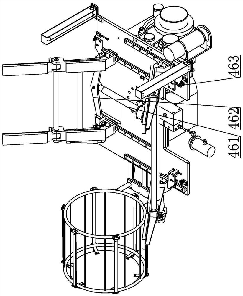
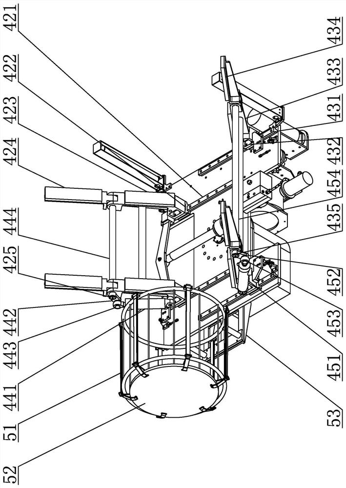
[0030] Specific implementation mode one: combine Figure 1 to Figure 7 Describe this embodiment, a kind of unmanned underwater vehicle grasping release device of this embodiment, it comprises manipulator rotating drive assembly, manipulator and clamping object end limiter 5, the power output end of manipulator rotating drive assembly and manipulator The bottom of the manipulator is connected, and the rotation of the manipulator is realized under the drive of the manipulator rotation drive assembly; the end stopper 5 of the clamped object includes an end limit cylinder 51, a limit cylinder cover 52 and a limit cylinder bracket 53, and the end limit cylinder 51 It is a cylindrical hollow structure, and the end limit cylinder 51 is horizontally arranged on one side of the manipulator along the length direction. The end limit cylinder 51 is installed on the manipulator through the limit cylinder bracket 53. The opening of the end limit cylinder 51 faces the manipulator. Limit cyli...
specific Embodiment approach 2
[0031] Specific implementation mode two: combination Figure 1 to Figure 7 Describe this embodiment. The manipulator rotation drive assembly in this embodiment includes a manipulator rotation drive hydraulic motor and a motor housing. The motor housing is installed on the connecting plate of the upper-level mechanical arm. The manipulator rotates and drives the hydraulic motor. The output shaft of the hydraulic motor is arranged vertically, and the manipulator rotates to drive the output shaft of the hydraulic motor to be connected with the manipulator.
[0032] So set, the manipulator rotates and drives the hydraulic motor to drive the manipulator to realize the rotation. Other compositions and connections are the same as in the first embodiment.
specific Embodiment approach 3
[0033] Specific implementation mode three: combination Figure 1 to Figure 7 Describe this embodiment, each little finger clamping assembly 42 of this embodiment comprises little finger slide rail 421, little finger slider 422, little finger base section 423, little finger end section 424 and little finger connecting shaft 425, and little finger slide rail 421 is along the robot palm 41 The width direction is horizontally installed on the upper surface of the mechanical palm 41. The bottom of the little finger slider 422 is provided with a chute that slides with the little finger slide rail 421. The little finger slider 422 is slidably installed on the little finger slide rail 421. The vertical direction is obliquely arranged above the little finger slider 422, the bottom of the little finger base section 423 is connected with the little finger slider 422, and the upper part of the little finger base section 423 is provided with two little finger connecting ear plates, and the ...
PUM
 Abstract
Description
Claims
Application Information
 - Generate Ideas
- Intellectual Property
- Life Sciences
- Materials
- Tech Scout
- Unparalleled Data Quality
- Higher Quality Content
- 60% Fewer Hallucinations
Browse by: Latest US Patents, China's latest patents, Technical Efficacy Thesaurus, Application Domain, Technology Topic, Popular Technical Reports.
© 2025 PatSnap. All rights reserved.Legal|Privacy policy|Modern Slavery Act Transparency Statement|Sitemap|About US| Contact US: help@patsnap.com