
Roller clamping type automobile metal plate repairing equipment

A clamping and automotive technology, applied in the direction of metal processing equipment, feeding devices, positioning devices, etc., can solve the problems of low efficiency of straight sheet metal, inability to use multiple angles, inconvenient operation by personnel, etc., and achieve structural Simple, hand-held effect

Inactive Publication Date: 2021-08-13
谈连美
View PDF4 Cites 0 Cited by
  • Summary
  • Abstract
  • Description
  • Claims
  • Application Information

AI Technical Summary

Problems solved by technology

[0002] There are many shortcomings in the existing equipment. When repairing some straight sheet metals, it is necessary to use the clamping rollers to clamp and then repair and return to normal. During this process, the operation is very inconvenient, resulting in The efficiency of actually repairing the straight sheet metal is low, and because the corresponding equipment cannot be self-locked after turning to a certain angle, the equipment cannot be used at multiple angles when it is actually used. The position of some straight plate-shaped sheet metal parts is not convenient for personnel to extend into the operation, and the corresponding pressing structure needs to be converted from multiple angles before it can be offset and clamped accordingly. It is precisely because of the above shortcomings that, The reliability and practicability of the actual use of existing equipment have been greatly reduced, and the efficiency of personnel to perform corresponding sheet metal repairs has been reduced due to the existence of the above shortcomings.

Method used


Image

  • Roller clamping type automobile metal plate repairing equipment
  • Roller clamping type automobile metal plate repairing equipment
  • Roller clamping type automobile metal plate repairing equipment

Examples


Embodiment Construction

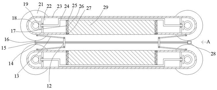
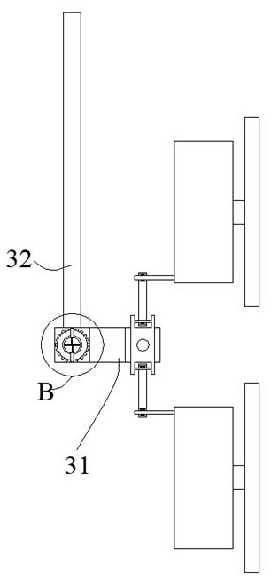
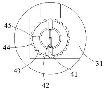
[0023] Such as Figure 1-Figure 6 As shown, the present invention is described in detail. For the convenience of description, the orientations mentioned below are now stipulated as follows: figure 1 The up, down, left, right, front and back directions of the projection relationship are the same. The roller clamping type automobile sheet metal repair equipment of the present invention includes two connection boxes 23, and the rotation inside the connection box 23 is provided with a pressing wheel 21, and the connection A matching box 16 is arranged between the box bodies 23, and a pressing block 29 is provided for sliding in the connecting box body 23, and symmetrical pressing wheels 21 are arranged for rotating on both sides of the connecting box body 23. A linkage device for linkage between the pressing wheel 21 and the pressing block 29 is provided between the pressing wheel 21 and the pressing block 29, and a linkage device is arranged between the matching box 16 and the co...


PUM


Abstract

The invention discloses roller clamping type automobile metal plate repairing equipment which comprises two connecting box bodies. Compressing wheels are rotatably arranged in the connecting box bodies; a matching box body is arranged between the connecting box bodies; pressing blocks are slidably arranged in the connecting box bodies; the symmetrical compressing wheels are rotatably arranged on the two sides of the connecting box bodies; linkage devices enabling the compressing wheels and the pressing blocks to be in linkage are arranged between the compressing wheels and the pressing blocks; and adjusting device for adjusting the sizes of the connecting box bodies relative to the matching box body so that the compressing wheels can clamp overturned edges of different specifications are arranged between the matching box body and the connecting box bodies. The equipment can adjust the distance between the compressing wheels so that the compressing wheels can clamp the different overturned edges; and in the operation process of the compressing wheels, the pressing blocks can be used for periodically compressing the overturned edges, a rotating rod can be directly used for rotating to multiple angles and then locking is conducted, and hand holding operation of personnel is facilitated.

Description

technical field [0001] The invention relates to the technical field of automobile sheet metal repair equipment, in particular to roller clamping type automobile sheet metal repair equipment. Background technique [0002] There are many shortcomings in the existing equipment. When repairing some straight sheet metals, it is necessary to use the clamping rollers to clamp and then repair and return to normal. During this process, the operation is very inconvenient, resulting in The efficiency of actually repairing the straight sheet metal is low, and because the corresponding equipment cannot be self-locked after turning to a certain angle, the equipment cannot be used at multiple angles when it is actually used. The position of some straight plate-shaped sheet metal parts is not convenient for personnel to extend into the operation, and the corresponding pressing structure needs to be converted from multiple angles before it can be offset and clamped accordingly. It is precise...

Claims


Application Information

Patent Timeline
IPC IPC(8): B21D1/00B21D43/00
CPCB21D1/00B21D43/003
Inventor 谈连美
Owner 谈连美
Learn More