
Highway camera with cleaning structure

A highway and camera technology, applied in image communication, camera body, cleaning methods and utensils, etc., can solve the problems of dust on the camera lens, increase the labor intensity, and the cleaning effect is not ideal, etc. the effect of clarity

Pending Publication Date: 2021-08-10
NINGBO CITY COLLEGE OF VOCATIONAL TECH
View PDF0 Cites 3 Cited by
  • Summary
  • Abstract
  • Description
  • Claims
  • Application Information

AI Technical Summary

Problems solved by technology

However, during the use of existing high-speed surveillance cameras, due to the long-term exposure of the camera to the outdoors, the camera lens is covered with dust. If manual cleaning is used, the labor intensity of labor will be greatly increased; some use additional equipment outside the lens for cleaning. However, since the cleaning equipment is also exposed to the air, the cleaning effect is not very satisfactory

Method used


Image

  • Highway camera with cleaning structure

Examples


Embodiment 1

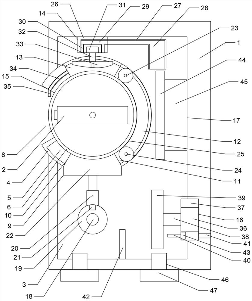
[0018] Embodiment 1: see figure 1, in this embodiment, since the camera is located in the spherical transparent cover. The dust on the highway will not have any contact with the body of the camera, and the dust will directly fall on the outer wall of the spherical transparent cover. Therefore, in this embodiment, it is only necessary to clean the spherical transparent cover. At the same time, since the spherical transparent cover is a transparent cover made of plastic, any rotation of the spherical transparent cover will not affect the normal operation of the camera. In this embodiment, when the spherical transparent cover needs to be cleaned, the first motor in the first accommodating cavity will rotate the first rotating shaft to make the spherical transparent cover roll circumferentially in the spherical accommodating cavity, When the part of the spherical transparent cover that needs to be cleaned is rotated to the first cleaning mechanism, the cylinder in the first fixe...


PUM


Abstract

The invention discloses a highway camera with a cleaning structure, and the camera comprises a shell and a camera, the shell is internally provided with a first accommodating cavity, the inner side wall of the first accommodating cavity is fixedly connected with a first shell, the first shell is internally provided with a spherical accommodating cavity, and the spherical accommodating cavity is internally slidably connected with a spherical transparent cover body; a camera is arranged in the spherical transparent cover, a second through hole for the camera to shoot is formed in the outer side wall of the left side of the first shell, a first cleaning mechanism is rotationally connected into the first containing cavity, a third through hole for the first cleaning mechanism to stretch into the spherical containing cavity is formed in the outer side wall of the lower end of the first shell, and a fourth through hole is formed in the right side of the first shell. A wiping mechanism is slidably connected into the fourth through hole, a fifth through hole is formed in the upper end face of the first shell, an air drying mechanism is arranged in the fifth through hole, a water mist removing mechanism is arranged in the second through hole, and a second cleaning mechanism capable of cleaning the first cleaning mechanism is arranged in the first containing cavity. A drying mechanism capable of drying the wiping mechanism is further arranged in the first containing cavity.

Description

technical field [0001] The invention relates to the technical field of high-speed cameras, in particular to a highway camera with a built-in cleaning structure. Background technique [0002] Surveillance cameras on highways are particularly important in daily life. On the one hand, the existence of high-speed surveillance cameras has greatly affected the crowds in the high-speed range. At the same time, high-speed cameras are also a necessary tool for the police to detect cases. As we all know, there are more vehicles on the highway, and there will be more dust during the driving process of the vehicles. However, during the use of existing high-speed surveillance cameras, since the camera is exposed to the outside for a long time, the camera lens is covered with dust. If manual cleaning is used, the labor intensity of labor will be greatly increased; some use additional equipment outside the lens for cleaning. But because the cleaning equipment is also exposed in the air, t...

Claims


Application Information

Patent Timeline
IPC IPC(8): H04N5/225B08B1/04G03B17/55
CPCG03B17/55H04N23/52H04N23/51B08B1/32
Inventor 张兆龙袁琪朗
Owner NINGBO CITY COLLEGE OF VOCATIONAL TECH
Learn More