
A flameproof three-phase motor

A three-phase motor, explosion-proof technology, applied in the field of electric motors, can solve the problems of unsafe and reliable use, hidden dangers of user safety, high internal temperature, etc., and achieve the effects of stable and safe operation, convenient and stable installation, and convenient explosion-proof treatment

Active Publication Date: 2022-05-20
ANHUI DALAI MOTOR CO LTD
View PDF6 Cites 0 Cited by
  • Summary
  • Abstract
  • Description
  • Claims
  • Application Information

AI Technical Summary

Problems solved by technology

[0004] The purpose of the present invention is to provide a flameproof three-phase motor to solve the problem that the internal temperature of the three-phase motor proposed in the above background technology is too high due to high-speed operation, and there is a danger of explosion, which will cause problems for users when using it. Certain potential safety hazards, problems that are not safe and reliable to use

Method used


Image

  • A flameproof three-phase motor
  • A flameproof three-phase motor
  • A flameproof three-phase motor

Examples


specific Embodiment approach 1

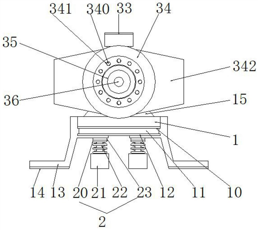
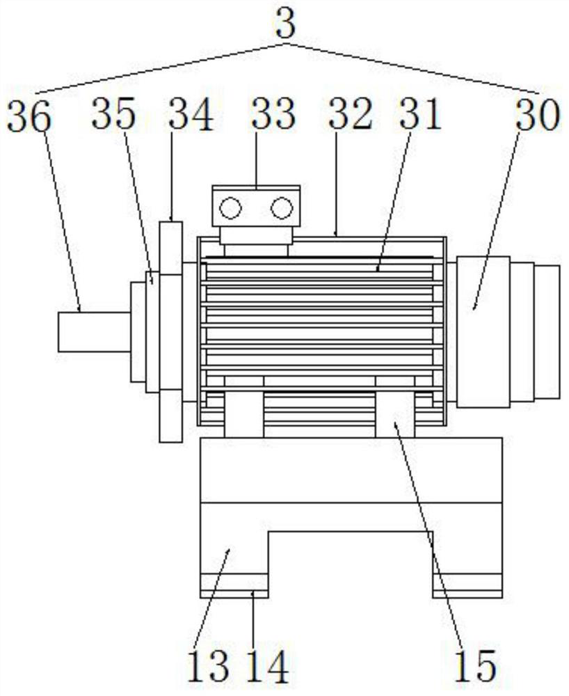
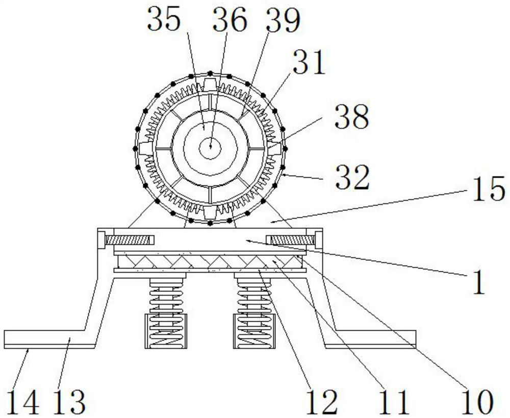
[0030] Specific embodiment of one, see Figure 1-7 , the present invention provides a flameproof three-phase motor, comprising a base 1, a shock absorption mechanism 2 and a motor structure 3, the base 1 is installed on the motor structure 3, the upper end of the middle of the motor structure 3 is provided with a junction box 33, and the inner bottom of the base 1 is installed on the front side and the rear side of the two sets of shock absorption mechanism 2, the front side of the motor structure 3 is provided with a protective panel 34, the middle of the protective panel 34 is provided with multiple sets of screw holes 341, and the screw hole 341 is installed with fastening screws 340, And the left and right sides of the protective panel 34 are provided with fixed side plates 342, and the center of the protective panel 34 is provided with a front sealing plate 35, and the center of the front sealing plate 35 is installed with a front shaft 36, the external of the motor structure ...

specific Embodiment approach 2

[0031]Specific embodiment two, the present invention is provided mainly for supporting the motor structure 3, while the bottom of the base 1 is provided on the anti-slip pad 10, buffer layer 11 and lower anti-slip pad 12, the upper anti-slip pad 10 and the lower anti-slip pad 12 is provided for anti-slip treatment, so that the installation of the buffer layer 11 can not be relaxed, and the use of the buffer layer 11 to effectively reduce the buffer, convenient and better stability of the motor.

specific Embodiment approach 3

[0032] Specific embodiment three, the present invention in the base 1 of the bottom front side and the rear side are installed on the shock absorption mechanism 2, the upper and lower ends of the shock absorption mechanism 2 are provided with a top plate 23 and a guide sleeve 21, the top plate 23 under the positioning rod 22 sets placed in the shock absorbing spring 20, helps to carry out straight directional shock absorption, can buffer a part of the vibration impact in the vertical direction, so that the equipment storage is more stable and safe.


PUM


Abstract

The invention discloses an explosion-proof three-phase motor, which comprises a base, a shock absorbing mechanism and a motor structure. A fixed side plate is provided, and the center of the protective panel is provided with a front sealing plate, and the center of the front sealing plate is installed with a front rotating shaft, and a first flameproof structure is installed outside the motor structure, and the first flameproof structure is installed There is a second flameproof structure, and a third flameproof structure is arranged outside the second flameproof structure. The invention utilizes the base to reduce vibration buffering and stabilize support, and the middle part of the motor structure is sequentially set with a first explosion-proof structure, a second explosion-proof structure and a third explosion-proof structure. High, and the flameproof strength is higher, the use is safer and more reliable, and the user is more at ease in use. At the same time, the rear part of the motor structure is convenient for heat dissipation.

Description

Technical field [0001] The present invention relates to a motor-related technical field, specifically a flameproof three-phase motor. Background [0002] Three-phase motor refers to when the three-phase stator winding of the motor, each with a difference of 120 degrees of electrical angle, after entering the three-phase alternating current, a rotating magnetic field will be generated, the rotating magnetic field cuts the rotor winding, thereby generating induced current in the rotor winding, the rotor winding is a closed path, the current-carrying rotor conductor will generate electromagnetic force under the action of the stator rotating magnetic field, thereby forming an electromagnetic torque on the motor shaft, driving the motor rotation, and the motor rotation direction is the same as the rotating magnetic field direction. [0003] However, due to the high-speed operation of the three-phase motor of the prior art, the internal temperature is too high, there will be a risk of ...

Claims


Application Information

Patent Timeline
Patent Type & Authority Patents(China)
IPC IPC(8): H02K5/24H02K5/10H02K5/136H02K5/04H02K5/00
CPCH02K5/24H02K5/10H02K5/136H02K5/04H02K5/00
Inventor 郑连玉
Owner ANHUI DALAI MOTOR CO LTD
Learn More