Temperature sensor dynamic calibration method based on dual temperature excitation

A temperature sensor, dynamic calibration technology, applied in thermometer testing/calibration, thermometers, instruments, etc., can solve problems such as time constant change, and achieve the effect of reducing uncertainty, suitable for promotion, and easy to operate

Active Publication Date: 2021-08-10
CHINA JILIANG UNIV
View PDF5 Cites 0 Cited by
  • Summary
  • Abstract
  • Description
  • Claims
  • Application Information

AI Technical Summary

Problems solved by technology

According to the current "JJF 1049-1995 Calibration Specification for Dynamic Response of Temperature Sensors", the dynamic calibration of temperature sensors mainly adopts the oil bath / water bath method and the hot wind tunnel method. The calibration methods for high-temperature fast response speed are mainly shock tube method and pulsed laser method, but there is a repeatability problem in the dynamic calibration of sensors applied in fast-response environments or non-fast-response environments, that is, using the same method for the same temperature When the sensor is calibrated multiple times, whether the peak fluctuation of the sensor response curve is within the allowable range of error, especially when the response curve is a unit impulse response curve, a small fluctuation of its peak value will cause a large change in the time constant

Method used


Image

  • Temperature sensor dynamic calibration method based on dual temperature excitation
  • Temperature sensor dynamic calibration method based on dual temperature excitation
  • Temperature sensor dynamic calibration method based on dual temperature excitation

Examples


Embodiment

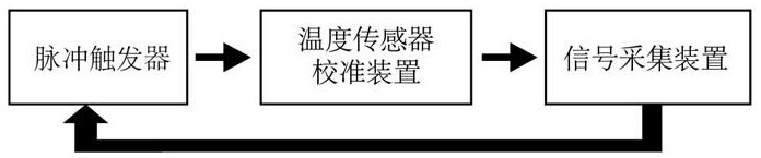
[0027] Example: see figure 1 , first install the temperature sensor to be calibrated on the temperature sensor calibration transposition, connect the lead wire of the temperature sensor to the signal acquisition device, then use the pulse trigger to generate a pulse signal A, trigger the temperature sensor calibration device to give a temperature excitation to the sensor to be calibrated, Use the temperature sensor signal acquisition device to collect the response signal a of the first temperature excitation of the sensor. After an interval of 1s, the pulse trigger generates the second pulse signal B, which triggers the temperature sensor calibration device to give the second temperature excitation to the temperature sensor to be calibrated. The sensor generates the response signal b of the second temperature excitation, and the response signal b is collected by the temperature sensor signal acquisition device. At this time, the time interval between the two response signals a ...


PUM


Abstract

The invention discloses a temperature sensor dynamic calibration method based on dual temperature excitation. According to the temperature sensor dynamic calibration method based on dual temperature excitation of the invention, by using the time interval between two response signals obtained after two temperatures excite a temperature sensor, the response speed range which can be measured by the dynamic calibration technology of the temperature sensor is improved. According to the method, the continuous approaching of the real time constant of the temperature sensor is realized gradually subtracting the time step s from the time interval of the pulse signals, and the mathematical model between relative deviation and critical relative deviation is established, so that the calibration precision of the time constant is improved.

Description

technical field [0001] The invention relates to the technical field of temperature sensor time constant calibration, in particular to a dynamic calibration method for a temperature sensor based on dual temperature excitation. Background technique [0002] A temperature sensor is a device that converts temperature into an electronic signal. It is widely used in modern industry. With the development of science and technology, there are more and more types of temperature sensors. According to the relationship between the temperature sensor and the measured object Relationships can be classified as contact and non-contact. But whether you use a contact temperature sensor or a non-contact temperature sensor for temperature measurement, if you want to get an accurate and reliable result, you must calibrate the temperature sensor. [0003] The calibration of the temperature sensor is divided into two parts: static calibration and dynamic calibration. The static calibration technol...

Claims


Application Information

Patent Timeline
IPC IPC(8): G01K15/00
CPCG01K15/005
Inventor 代明璐杨洪波杨逸宁潘婧涵陈维杰卓银杰刘彤彤刘烁贝凃程旭
Owner CHINA JILIANG UNIV
Why Eureka
Try Eureka