Eureka AIR delivers breakthrough ideas for toughest innovation challenges, trusted by R&D personnel around the world.

Pressurized carbonization device for bulk solid waste after alkalization treatment

A solid waste and alkalization treatment technology, which is applied in the direction of solid waste removal, transportation and packaging, chemical instruments and methods, etc., can solve the troublesome problems of putting into a pressurized carbonization device, inconvenient bulk solid waste, and transportation, etc., to achieve The processing process is perfect, the effect of carrying and simple operation is realized

Inactive Publication Date: 2021-08-10
张军强
View PDF3 Cites 1 Cited by
  • Summary
  • Abstract
  • Description
  • Claims
  • Application Information

AI Technical Summary

Problems solved by technology

[0006] It is inconvenient to carry the bulk solid waste after alkalization treatment, and it is very troublesome to put it into the pressurized carbonization device, so it needs to be improved

Method used


Image

  • Pressurized carbonization device for bulk solid waste after alkalization treatment
  • Pressurized carbonization device for bulk solid waste after alkalization treatment
  • Pressurized carbonization device for bulk solid waste after alkalization treatment

Examples


Embodiment 1

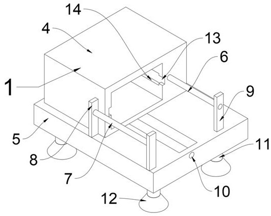
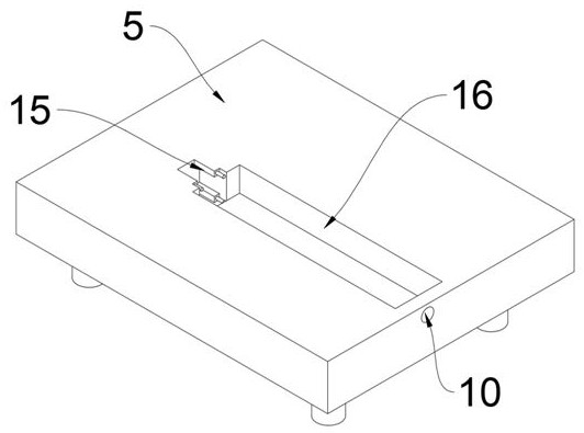
[0034] A pressurized carbonization device after alkalization treatment of bulk solid waste, such as figure 1 As shown, it includes a fixing device 1, the inside of the fixing device 1 is slidingly connected with a pushing device 2, and the inside of the pushing device 2 is clamped and fixed with a loading device 3, as figure 2 , 3As shown, the fixing device 1 includes a pressurized carbonization box 4, a bottom plate 5, a first connecting column 6, a second connecting column 7, a first positioning plate 8, a second positioning plate 9, a first positioning hole 10, a supporting column 11, The base 12, the first moving groove 13, the second moving groove 14, the mounting groove 15 and the positioning groove 16, the base plate 5 is arranged inside the fixing device 1, the support columns 11 are fixedly connected to the four corners of the lower end surface of the base plate 5, and the base 12 is fixed Connected to the lower end surface of the support column 11, the first positi...

Embodiment 2

[0038] On the basis of Example 1, such as Figure 7 , 8 As shown, the loading device 3 also includes a handle 36, a cover 37 and a positioning bar 38, the positioning bar 38 is slidably engaged with the upper end of the insertion block 33, the cover 37 is fixedly connected to the upper end surface of the positioning bar 38, and the handle 36 is fixed Connected to the middle part of the upper end face of the cover 37.

[0039] When this embodiment is in use, pull the handle 36 fixedly connected in the middle of the upper end surface of the cover 37, place the cover 37 on the upper end surface of the plug-in block 33, and the cover 37 is symmetrically fixed and connected to the positioning strip through the lower end surface of the cover 37 38 is clamped and fixed inside the plug-in block 33, so that the bulk solid waste after alkalization treatment inside the plug-in block 33 is isolated from the outside world, so that the alkalization treatment is repeated.


PUM


Abstract

The invention discloses a pressurized carbonization device for bulk solid waste after alkalization treatment. The pressurized carbonization device comprises a fixing device, the interior of the fixing device is slidably connected with a pushing device, and the interior of the pushing device is fixedly clamped with a loading device. The fixing device comprises a pressurizing carbonization box, a bottom plate, a first connecting column, a second connecting column, a first positioning plate, a second positioning plate, a first positioning hole, supporting columns, a base, a first moving groove, a second moving groove, a mounting groove and a positioning groove, the bottom plate is arranged in the fixing device, and the supporting columns are fixedly connected to the four corners of the lower end face of the bottom plate. The bases are fixedly connected to the lower end faces of the supporting columns, the first positioning plates are symmetrically and fixedly connected to one side of the front end of the bottom plate, and the second positioning plate is fixedly connected to the other side of the front end of the bottom plate. The invention relates to the pressurized carbonization device for bulk solid waste after alkalization treatment, and the bulk solid waste is eliminated through the fixing device.

Description

technical field [0001] The invention relates to the technical field of waste treatment equipment, in particular to a pressurized carbonization device for bulk solid waste after alkalization treatment. Background technique [0002] According to Chinese Patent No. CN206751417U, the present invention discloses a pressurized carbonization device for preparing nano-calcium carbonate, including a slurry feeding pipeline, a carbonization tower, a stirring device, a circulating emulsification pump, a circulating pipeline, a liquid flow meter, a pipeline mixing reactor, a kiln Gas storage tanks, air compressors, kiln gas inlet pipes, gas flow meters, etc. The device is used for carbonization for preparing nano-calcium carbonate, which has low energy consumption, low equipment investment, high carbonization efficiency, and easy control of the carbonization process. [0003] According to Chinese Patent No. CN108844888A, the present invention provides a pressurized carbonization device...

Claims


Application Information

Patent Timeline
Patent Type & Authority Applications(China)
IPC IPC(8): B09B3/00
CPCB09B3/00B09B3/40
Inventor 张军强
Owner 张军强
Why Eureka
Eureka Blog
Learn More