Switching power source

A switching power supply and switching device technology, applied in electrical components, regulating electrical variables, instruments, etc., can solve the problems of inability to guarantee zero-voltage switching of the first switching device, large ohmic loss, etc.

Inactive Publication Date: 2003-12-24
KONINKLIJKE PHILIPS ELECTRONICS NV
View PDF2 Cites 0 Cited by
  • Summary
  • Abstract
  • Description
  • Claims
  • Application Information

AI Technical Summary

Problems solved by technology

Especially at high output powers, the first switching element has the greatest ohmic losses, which can lead to the fact that no negative primary current

Method used


Image

  • Switching power source
  • Switching power source
  • Switching power source

Examples


Embodiment Construction

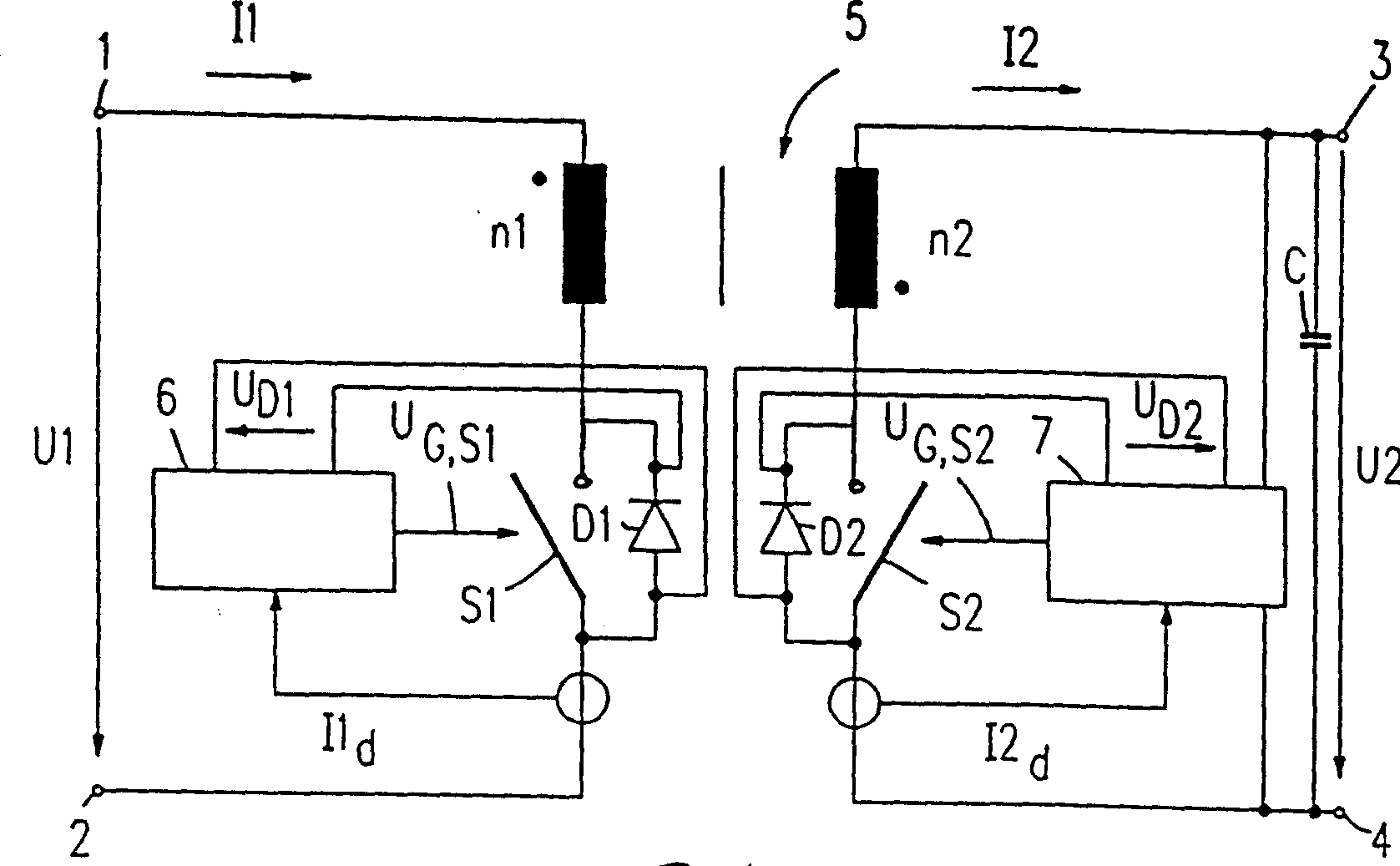
[0020] figure 1 The shown bidirectional flyback converter type switching power supply has two input terminals 1 and 2 at its input, between which the input voltage U1 is applied. The input terminal 1 , which has a positive potential than the input terminal 2 , is connected to the primary winding of the transformer 5 having n1 turns. The other connection of the primary winding is connected to switching device S1 in parallel with diode D1. The switching device S1 is, for example, a MOS (Metal-Oxide-Semiconductor) field effect transistor. In this case, the so-called body diode of the field effect transistor can be used as diode D1. The cathode of diode D1 is connected to the primary winding of transformer 5 and the anode of diode D1 is connected to input terminal 2 such that the parallel combination of switching device S1 and diode D1 is between the primary winding of transformer 5 and input terminal 2 . The switching position of the switching device S1 is controlled by the co...


PUM


Abstract

The invention relates to a switched mode power supply comprising a transformer (5) having a primary winding to which a first switching device (S1) is connected, and a secondary winding to which a second switching device (S2) is connected, when in operation, first periods of time (A) with a primary current (I1) flowing through the primary winding alternate with second periods of time (B) with a secondary current (I2) flowing through the secondary winding. A secondary-side control unit (7) is provided for controlling the output voltage (U2) or the output current of the switched mode power supply by adaptation of the return of part of the energy supplied by the transformer in the second periods of time (B). A primary-side control unit (6) is provided which is used for controlling the energy supplied by the transformer (5) in the direction of the input of the switched mode power supply in the first periods of time (A) to a predefined value.

Description

technical field [0001] The present invention relates to a switching power supply comprising a transformer having a primary winding connected in series with a first switching device and a secondary winding connected in series with a second switching device, wherein when the switching power supply is in operation, the primary current flows through the first winding of the primary winding A time period alternates with a second time period in which the secondary current flows through the secondary winding, and wherein secondary side control means are provided for controlling a portion of the energy supplied by the transformer in the output direction of the switching power supply in the second The time period returns the adaptation of the transformer to control the output voltage or output current of the switching power supply. [0002] Such switching power supplies are particularly suitable in the low and medium power range (up to several hundred watts) as bidirectional switching ...

Claims


Application Information

Patent Timeline
IPC IPC(8): H02M3/28H02M3/335H02M7/12
CPCH02M3/33584H02M7/12
Inventor T·迪尔鲍姆
Owner KONINKLIJKE PHILIPS ELECTRONICS NV
Why Eureka
Try Eureka