
Fluidized bed furnace

A technology of fluidized bed furnace and slag, which is applied in the direction of incinerator, fluidized bed combustion equipment, fuel burning in molten state, etc. It can solve the problems of stable combustion of fuel, hindering the flow of fluidized layer, etc., and achieve the purpose of suppressing lumps Effect

Pending Publication Date: 2021-08-06
KAWASAKI HEAVY IND LTD
View PDF5 Cites 0 Cited by
  • Summary
  • Abstract
  • Description
  • Claims
  • Application Information

AI Technical Summary

Problems solved by technology

If the flow medium becomes agglomerated in this way, the smooth flow of the fluid bed will be hindered, and stable combustion of the fuel will become difficult.

Method used


Image

  • Fluidized bed furnace
  • Fluidized bed furnace
  • Fluidized bed furnace

Examples


Embodiment Construction

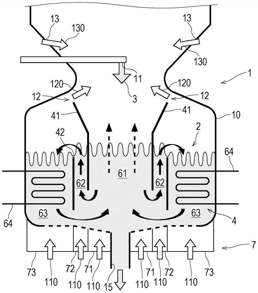
[0025] Next, embodiments of the present invention will be described with reference to the drawings. figure 1 It is a schematic structural diagram of the fluidized-bed furnace 1 which concerns on one Embodiment of this invention. figure 1 The illustrated fluidized bed furnace 1 is an internal circulation fluidized bed type fluidized bed furnace 1 . However, in the present invention, the fluidized bed furnace 1 is not limited. In addition to the internal circulating fluidized bed type, it can also be used in various known forms such as the usual bubbly fluidized bed type, high-speed fluidized bed type, and external circulating fluidized bed type. The invention is applied in a fluidized bed furnace.

[0026] The fluidized bed furnace 1 has a combustion vessel 10 . In the fluidized bed furnace 1, the internal circulation flow layer 2 is formed by the partition walls 41, 42, the flow medium 4 and the fluidization gas supply device 7, wherein the partition walls 41, 42 divide the ...


PUM

PropertyMeasurementUnit
heating valueaaaaaaaaaa
particle sizeaaaaaaaaaa

Abstract

This fluidized bed furnace which burns a fuel containing an alkali metal is provided with a fluidized bed that burns a fuel supplied thereto by fluidizing a fluid medium. The fuel contains an alkali metal. The fluid medium is composed of a particulate mineral and / or a particulate slag, while having a quartz content of 14% by mass or less.

Description

technical field [0001] The present invention relates to a fluidized bed furnace for combusting a fuel comprising an alkali metal. Background technique [0002] In recent years, biomass has been recognized as one of the powerful renewable energy sources. For example, in biomass power generation, steam or gas generated by burning biomass fuel is used to rotate a turbine to generate power. For burning biomass fuel, for example a fluidized bed furnace is used. The fluidized bed furnace has a fluidized bed in which a high-temperature fluid medium flows by blown pressurized air, and the supplied fuel is burned in the fluidized bed. As the above-mentioned fluid medium, silica sand is generally used. Silica sand refers to sand mainly composed of quartz grains. [0003] Among the biomass, the use of palm coconut empty fruit bunches (EFB: Empty Fruit Bunches), which has been discarded in the past, has also attracted attention. EFB is an effective fuel with a water content of abou...

Claims


Application Information

Patent Timeline
Patent Type & Authority Applications(China)
IPC IPC(8): F23C10/01F23G7/00F23C10/18
CPCF23C10/01F23C10/18F23G7/00
Inventor 五十岚实小川祐司清水敬哲武藤贞行清泷元饭田雄介
Owner KAWASAKI HEAVY IND LTD
Learn More