Intelligent environment-friendly solid insulation ring main unit with good anti-seismic effect
A technology with anti-seismic effect and solid insulation, applied in the field of ring network cabinets, can solve the problems of reducing the service life and replacement cycle of internal components of the ring network cabinet, increasing the maintenance and replacement costs of internal components, poor anti-seismic effect, etc., so as to improve the anti-seismic effect, Efforts to simplify installation and removal processes and improve repair and replacement costs
- Summary
- Abstract
- Description
- Claims
- Application Information
AI Technical Summary
Problems solved by technology
Method used
Image
Examples
Embodiment 1
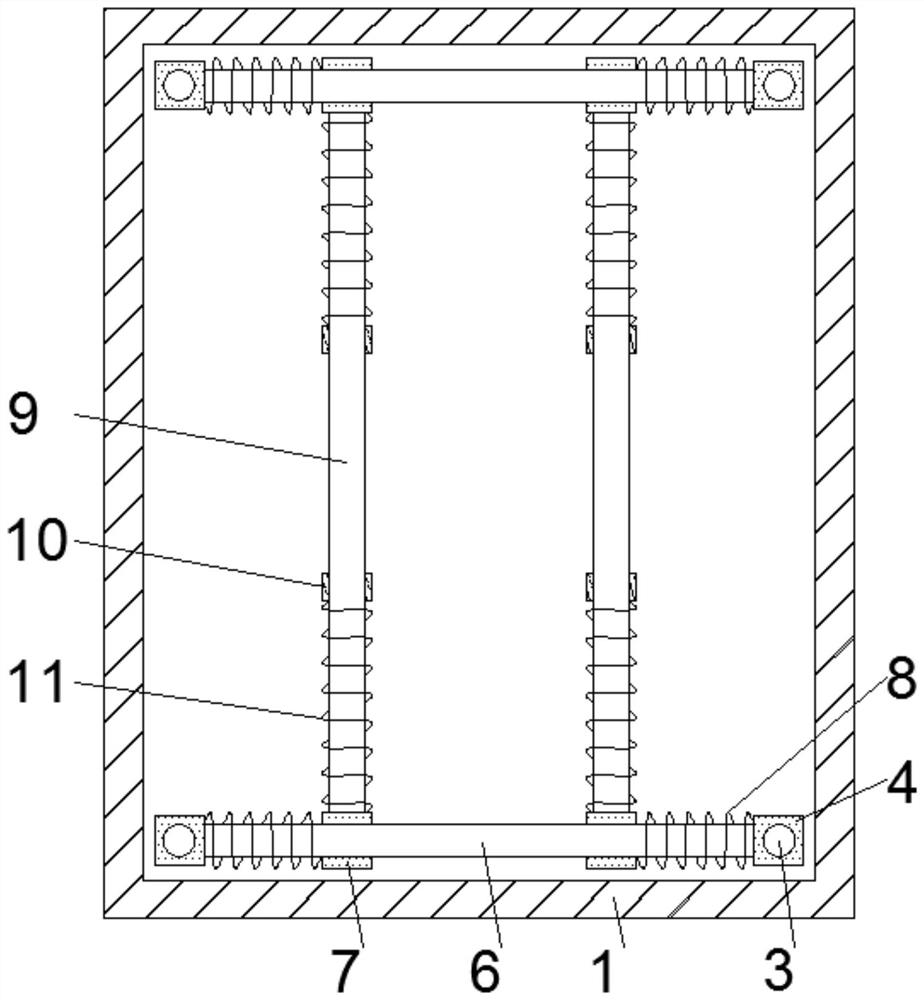
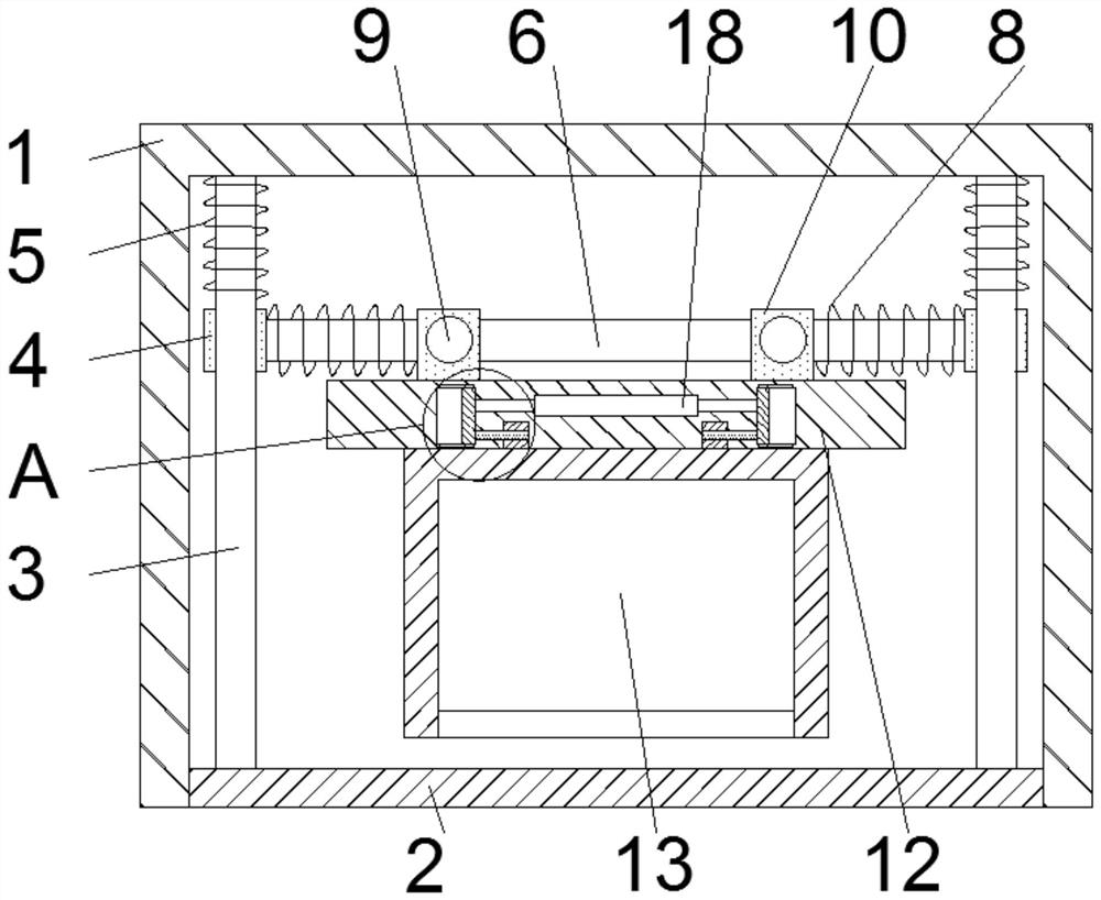
[0025] see Figure 1-5 According to an embodiment of the present invention, an intelligent environment-friendly solid insulation ring network cabinet with good anti-seismic effect includes an outer box 1, and both ends of one side of the outer box 1 are fixedly connected with a fixing plate 2, and the fixing plate 2 One side of one side is fixedly connected with a quantity of two slide bars one 3, and one end of the slide bar one 3 away from the fixed plate 2 is fixedly connected with the outer box 1, and the outer surfaces of the slide bar one 3 all slide A sliding sleeve 4 is connected, one side of the sliding sleeve 4 is fixedly connected with a spring 5, and the side of the spring 5 away from the sliding sleeve 4 is fixedly connected with the outer box 1, and the spring 5 One 5 is sleeved on the outer surface of the sliding rod one 3, and the two sliding sleeves one 4 are fixedly connected by the sliding rod two 6, and the outer surfaces of the sliding rod two 6 are slidin...
Embodiment 2
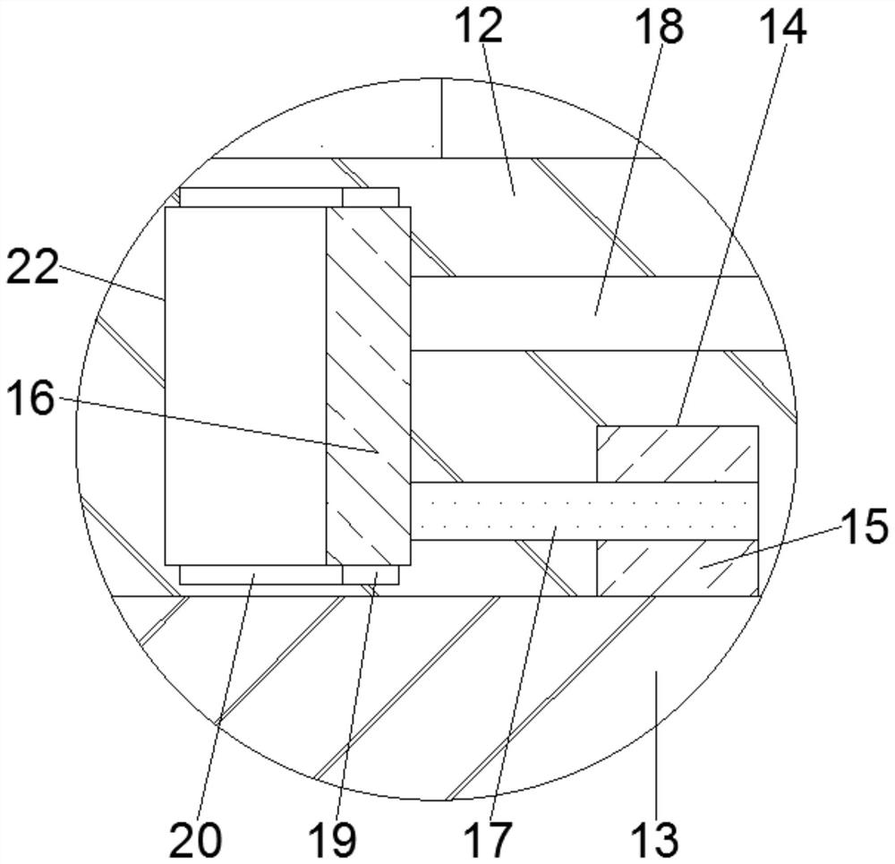
[0027] see Figure 1-5 One side of the installation plate 12 is provided with two installation grooves 14, and the side of the ring network cabinet 13 close to the installation grooves 14 is fixedly connected with a block 15, and the block 15 is connected to the The mounting groove 14 is compatible, and the mounting plate 12 is provided with a mounting mechanism. The mounting mechanism includes a cavity 22, a slide plate 16 and a fixed rod 17. cavity 22, a slide plate 16 is slidably connected in the cavity 22, and one side of the slide plate 16 is fixedly connected with three fixed rods 17, and the side of the fixed rod 17 away from the slide plate 16 runs through the The mounting plate 12 extends to the clamping block 15, and the fixed rod 17 is slidably connected with the mounting plate 12, which simplifies the installation and disassembly process and improves work efficiency. The fixed rod 17 and the clamping block 15 Compatible, stable installation.
Embodiment 3
[0029] see Figure 1-5 , the middle part of the mounting plate 12 is fixedly connected with a double-headed non-standard hydraulic cylinder 18, and the telescopic end of the double-headed non-standard hydraulic cylinder 18 is fixedly connected with the slide plate 16, and simultaneously promotes the horizontal movement of the slide plate 16, and the slide plate Both sides of 16 are fixedly connected with sliders 19, and the cavity 22 is provided with a chute 20 near the slider 19, and the slider 19 is slidably connected with the chute 20 to reduce friction and wear. A box door 21 is hingedly connected between the two fixing plates 2 .
[0030] In order to facilitate the understanding of the above-mentioned technical solution of the present invention, the working principle or operation mode of the present invention in the actual process will be described in detail below.
[0031] In actual application, snap the block 15 on the ring network cabinet 13 into the installation groo...
PUM
 Abstract
Description
Claims
Application Information
 - R&D
- Intellectual Property
- Life Sciences
- Materials
- Tech Scout
- Unparalleled Data Quality
- Higher Quality Content
- 60% Fewer Hallucinations
Browse by: Latest US Patents, China's latest patents, Technical Efficacy Thesaurus, Application Domain, Technology Topic, Popular Technical Reports.
© 2025 PatSnap. All rights reserved.Legal|Privacy policy|Modern Slavery Act Transparency Statement|Sitemap|About US| Contact US: help@patsnap.com


