Direct-current combustor and boiler structure provided with direct-current combustors

A burner and boiler technology, which is applied to burners, combustion equipment, and combustion using various fuels, etc., can solve the problems of affecting the ignition and combustion of pulverized coal, unable to adjust and change the tangent circle, and high content of pulverized coal.

Pending Publication Date: 2021-08-06
SUZHOU XIRE ENERGY SAVING ENVIRONMENTAL PROTECTION TECH CO LTD +1
View PDF5 Cites 0 Cited by
  • Summary
  • Abstract
  • Description
  • Claims
  • Application Information

AI Technical Summary

Problems solved by technology

[0002] Pulverized coal burner refers to equipment that can fully burn pulverized coal in a short time and generate high-temperature vortex. The existing boilers equipped with DC pulverized coal burners are usually ignited by cutting the four corners to improve the efficiency of combustion and ignition. Efficiency, at this time, the interior of the burner is equipped with multi-stage wind to comprehensively act on the pulverized coal, mainly through the action of the secondary air to gather the pulverized coal to ensure the temperature of the flame core and the range of combustion. However, in this way, the ignition The device is not easy to act on the peripheral side of the pulverized coal, and the pulverized coal content in the center of the pulverized coal is high, which is not conducive to the normal ignition of the equipment
Existing equipment cannot be adjusted in time to change the size of the tangent circle for changing coal types, which will affect the ignition and combustion of pulverized coal, resulting in insufficient combustion and low boiler efficiency

Method used


Image

  • Direct-current combustor and boiler structure provided with direct-current combustors
  • Direct-current combustor and boiler structure provided with direct-current combustors
  • Direct-current combustor and boiler structure provided with direct-current combustors

Examples


Embodiment Construction

[0030] The technical solutions of the present invention will be clearly and completely described below in conjunction with the accompanying drawings. Apparently, the described embodiments are some of the embodiments of the present invention, but not all of them. Based on the embodiments of the present invention, all other embodiments obtained by persons of ordinary skill in the art without making creative efforts belong to the protection scope of the present invention.

[0031] In the description of the present invention, it should be noted that the terms "center", "upper", "lower", "left", "right", "vertical", "horizontal", "inner", "outer" etc. The indicated orientation or positional relationship is based on the orientation or positional relationship shown in the drawings, and is only for the convenience of describing the present invention and simplifying the description, rather than indicating or implying that the referred device or element must have a specific orientation, ...


PUM


Abstract

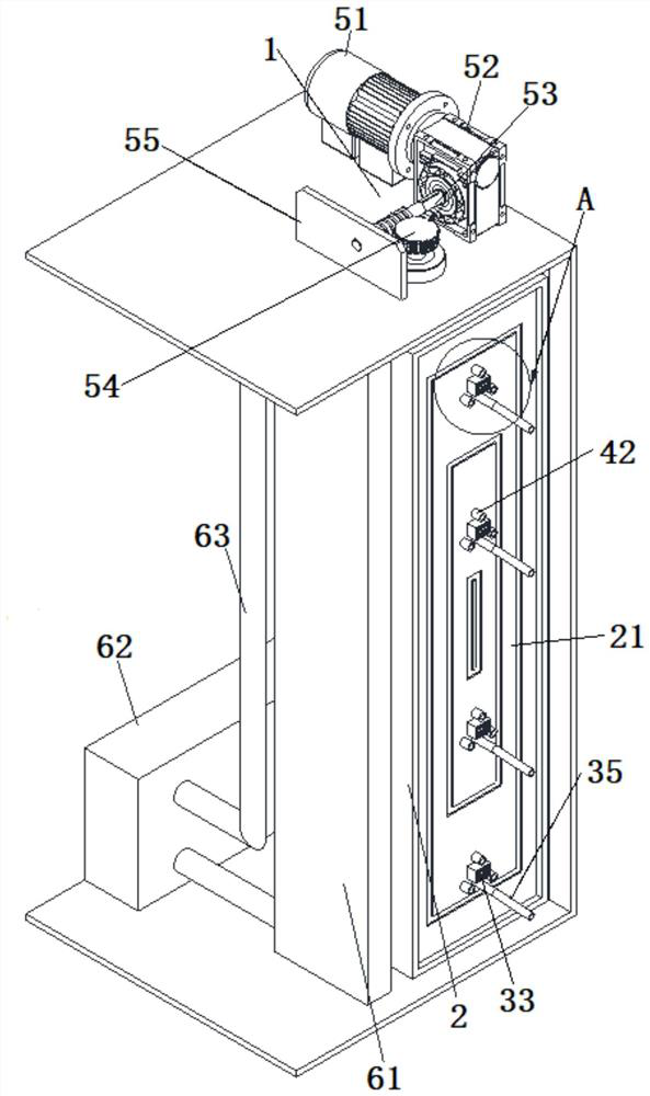
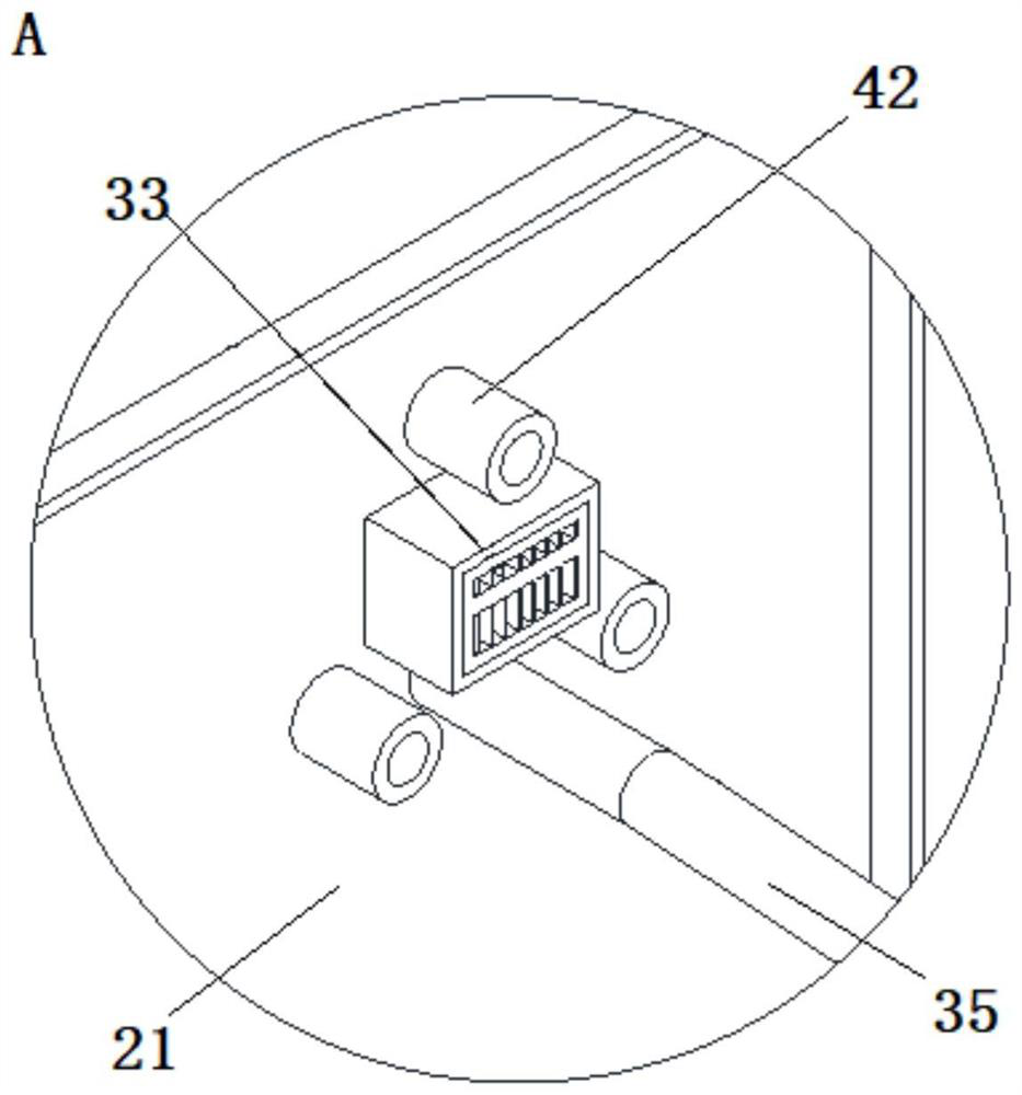
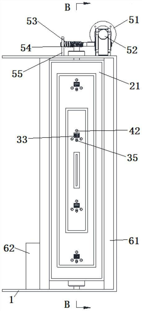
The invention relates to a direct-current combustor. The combustor comprises a shell, wherein the shell is provided with a panel located on the front surface of the shell; a combustion unit, wherein the combustion unit comprises a main air inlet pipe and multiple spraying assemblies, each spraying assembly comprises a spraying pipe and an ignition system, the spraying pipes are communicated with the main air inlet pipe, and the outlet ends of the spraying pipes and the ignition systems are arranged on the panel; a rotation driving unit, wherein the rotation driving unit is used for driving the panel to rotate and comprises a driving part, and the driving part is in transmission connection with the panel; and a protection unit, wherein the protection unit comprises a heat insulation part, and the heat insulation part is arranged on at least one side of the panel. A boiler structure provided with the direct-current combustors comprises a boiler and the direct-current combustors arranged on the periphery of the boiler in a surrounding mode, the panel is arranged towards a hearth of the boiler, and the heat insulation part is arranged between the panel and the boiler and attached to the panel and the boiler.

Description

technical field [0001] The invention relates to a coal-fired boiler, in particular to a direct-flow burner and a boiler structure provided with a direct-flow burner. Background technique [0002] Pulverized coal burner refers to equipment that can fully burn pulverized coal in a short time and generate high-temperature vortex. The existing boilers equipped with DC pulverized coal burners are usually ignited by cutting the four corners to improve the efficiency of combustion and ignition. Efficiency, at this time, the interior of the burner is equipped with multi-stage wind to comprehensively act on the pulverized coal, mainly through the action of the secondary air to gather the pulverized coal to ensure the temperature of the flame core and the range of combustion. However, in this way, the ignition The device is not easy to act on the peripheral side of the pulverized coal, and the pulverized coal content in the center of the pulverized coal is high, which is not conducive...

Claims


Application Information

Patent Timeline
IPC IPC(8): F23D1/00F23C5/08F23C5/06
CPCF23D1/00F23C5/08F23C5/06
Inventor 陈敏王小华陈宝康赵俊武梅振锋薛晓垒彭小敏俞胜捷刘瑞鹏赵鹏丁奕文朱晋永姚胜王祝成梁昊王晖
Owner SUZHOU XIRE ENERGY SAVING ENVIRONMENTAL PROTECTION TECH CO LTD
Why Eureka
Try Eureka