Gear convenient to lubricate

A technology of gears and gear teeth, which is applied in the field of gears that are easy to lubricate, can solve problems such as inability to lubricate gears, poor smooth performance, and low use strength, and achieve the effects of simple structure, uniform lubrication, and convenient operation

Inactive Publication Date: 2021-08-06
泰州市泰华齿轮制造有限公司
View PDF5 Cites 0 Cited by
  • Summary
  • Abstract
  • Description
  • Claims
  • Application Information

AI Technical Summary

Problems solved by technology

[0003] There are certain disadvantages in the existing gears in use. First, when in use, the gears cannot be easily lubricated, and the smooth performance is poor, which is not conducive to people's use. In addition, when in use, The use intensity is low, which brings certain adverse effects to people's use process. Therefore, we propose a gear that is easy to lubricate

Method used


Image

  • Gear convenient to lubricate
  • Gear convenient to lubricate
  • Gear convenient to lubricate

Examples


Embodiment 1

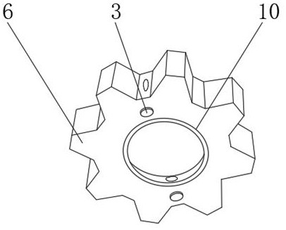
[0029] Such as Figure 1-4 As shown, a gear that is convenient for lubrication includes a rotating gear 1, a driving gear 6 and a gear body 9, a rotating shaft 8 is arranged between the driving gear 6 and the gear body 9, and a lubricating oil adding pipeline mechanism is positioned on the inner wall of the driving gear 6 3. The outer side of the driving gear 6 is fixedly connected with the No. 2 gear tooth 5, the inner wall of the rotating gear 1 is provided with a gear wall 2, the outer side of the rotating gear 1 is fixedly connected with the No. 1 gear tooth 4, and the outer surface of the rotating gear 1 is fixedly connected with an anti-corrosion The derusting strengthening mechanism 7, a bearing 10 is arranged between the drive gear 6 and the rotating shaft 8;

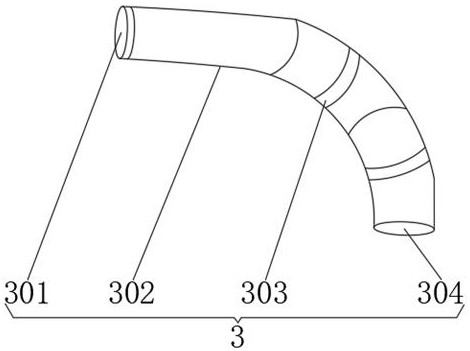
[0030] The lubricating oil adding pipeline mechanism 3 includes a sliding cover 301, a pipeline 302, a retaining member 303, an oil outlet 304, a sealing ring 305, and a drip irrigation port 306. The sliding cov...

Embodiment 2

[0034] Such as Figure 1-4 As shown, a gear that is convenient for lubrication includes a rotating gear 1, a driving gear 6 and a gear body 9, a rotating shaft 8 is arranged between the driving gear 6 and the gear body 9, and a lubricating oil adding pipeline mechanism is positioned on the inner wall of the driving gear 6 3. The outer side of the driving gear 6 is fixedly connected with the No. 2 gear tooth 5, the inner wall of the rotating gear 1 is provided with a gear wall 2, the outer side of the rotating gear 1 is fixedly connected with the No. 1 gear tooth 4, and the outer surface of the rotating gear 1 is fixedly connected with an anti-corrosion The derusting strengthening mechanism 7, a bearing 10 is arranged between the drive gear 6 and the rotating shaft 8;

[0035] The anti-corrosion and rust-removing strengthening mechanism 7 comprises an anti-corrosion layer 701, a rust-removing layer 702, a reinforcement layer 703, a wear-resistant layer 704, and a connecting lay...


PUM


Abstract

The invention discloses a gear convenient to lubricate. The gear convenient to lubricate comprises a rotating gear, a driving gear and a gear body, wherein a rotating shaft is arranged between the driving gear and the gear body, a lubricating oil adding pipeline mechanism is positioned and installed on the inner wall of the driving gear, and the outer side of the driving gear is fixedly connected with second gear teeth; and the inner wall of the rotating gear is provided with a gear wall, the outer side of the rotating gear is fixedly connected with first gear teeth, the outer surface of the rotating gear is fixedly connected with an anti-corrosion and rust-removal reinforcing mechanism, and a bearing is arranged between the driving gear and the rotating shaft. According to the gear convenient to lubricate, the lubricating oil adding pipeline mechanism and the anti-corrosion and rust-removal reinforcing mechanism are arranged, the gear can be conveniently and better lubricated, lubrication is uniform and can be kept for a certain time, the use strength of the gear can be improved, the gear has the anti-corrosion and rust-removal performance, the service life is prolonged, and a better use prospect is brought.

Description

technical field [0001] The invention relates to the field of gears, in particular to a gear that is easy to lubricate. Background technique [0002] A gear is a supporting device that rotates the driving parts. When the motor and other driving and rotating devices are used, the use of the gear is indispensable and plays a driving role. With the continuous development of science and technology, people have requirements for the manufacturing process of gears. Also getting higher and higher. [0003] There are certain disadvantages in the existing gears in use. First, when in use, the gears cannot be easily lubricated, and the smooth performance is poor, which is not conducive to people's use. In addition, when in use, The use intensity is low, which brings certain adverse effects to people's use process. Therefore, we propose a gear that is easy to lubricate. Contents of the invention [0004] (1) Solved technical problems [0005] Aiming at the deficiencies of the prior ...

Claims


Application Information

Patent Timeline
Patent Type & Authority Applications(China)
IPC IPC(8): F16H55/17F16H55/06F16H57/04
CPCF16H55/17F16H55/06F16H57/0427
Inventor 吴开忠丁国荣操伟
Owner 泰州市泰华齿轮制造有限公司
Why Eureka
Try Eureka