
Variable line girder numerical control driving system and working process thereof

A drive system and girder technology, applied to monorail systems, elevated railway systems with suspended vehicles, motor vehicles, etc., can solve problems such as the inability to ensure the accurate docking of switch rails and fixed rails, and achieve high reliability and improved Operational accuracy and improved reliability

Active Publication Date: 2021-08-06
YANSHAN UNIV
View PDF7 Cites 0 Cited by
  • Summary
  • Abstract
  • Description
  • Claims
  • Application Information

AI Technical Summary

Problems solved by technology

[0006]According to the prior art proposed above, when the box-shaped track girder with variable line opening is rotated to each working position, it cannot ensure the accurate docking of the switch line change rail and the fixed rail To solve the technical problems, and to provide a CNC drive system and its working process

Method used


Image

  • Variable line girder numerical control driving system and working process thereof
  • Variable line girder numerical control driving system and working process thereof
  • Variable line girder numerical control driving system and working process thereof

Examples


Embodiment 1

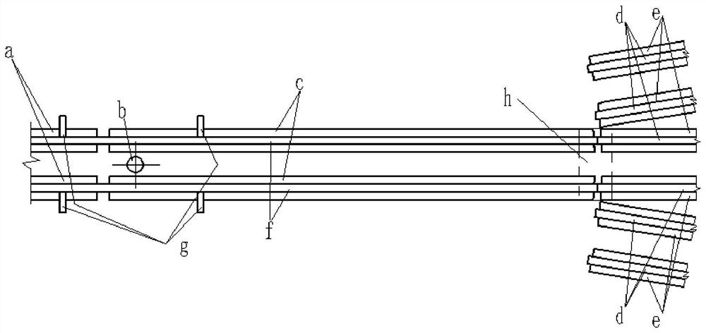
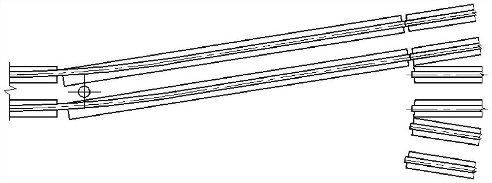
[0073] like Figure 1-2 shown in figure 1 In the structural schematic diagram of the suspended freight monorail three-opening turnout, the fixed monorail open box track beam a is two I-shaped beams ( Figure 1-2 Simplified in , the same below), the line-changing monorail open box track beam c is also two I-shaped beams arranged in parallel in space; the three-track open box track beam e is composed of six mutually fixed The two I-shaped girders in the center of the three-track open box track beam e are arranged in parallel in space; the two I-shaped girders on both sides are respectively arranged in parallel in space; the central I-shaped girder and the two sides The included angle between the I-shaped girders is just equal to the line change angle of the turnout. The two change-line rails f are respectively placed on the upper surface of the lower floor inside the I-shaped girder (inside the vertical plate of the I-shaped girder) of the fixed monorail open box track beam a ...

Embodiment 2

[0090] On the basis of Embodiment 1, the present invention also provides a working process of a line-changing girder numerical control drive system, including a debugging process and a working process.

[0091] 1. Debugging process

[0092] 1) Left working point setting

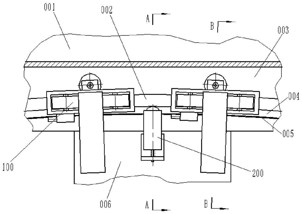
[0093] attached Figure 1 to Figure 11 As shown, the open box-shaped track beam 006 of the line-changing monorail is in the neutral position. Firstly, the two servo motors 125 are started at the same speed in the jogging mode, and the two driving wheels B127 are driven to rotate through the two reducers 124 and the two rotating shafts B129. , the two traveling wheels A121 also rotate at the same speed; thereby driving the line-changing monorail open box-type track beam 006 to turn counterclockwise through a three-way turnout angle, and observe the mutual position of the line-changing track f and the three-way switch rail d In this situation, the two servo motors 125 are repeatedly jogged in forward and reve...


PUM


Abstract

The invention discloses a variable line girder numerical control driving system and a working process thereof. Four walking wheels driven by a servo motor are arranged on an annular track to achieve line-changing motion, four guide wheels are used for guiding, and a magnetic ruler detection system and the servo motor form a closed-loop control system. Accurate fixed-angle rotation of a suspension type freight three-way turnout line changing beam can be achieved, the requirement for frequent track changing of suspension type freight train turnouts is met, reliability is high, and train operation is stable.

Description

technical field [0001] The invention relates to a numerically controlled drive system for a line-changing girder and its working process. Background technique [0002] The main feature of the suspended monorail transportation system is that the running part on the upper part of the vehicle is placed in the open box-shaped track beam, and the vehicle is suspended to run under the track beam. The suspended monorail transport moves the ground traffic to the air, making full use of the urban space. It is not easy to derail, strong climbing ability, small turning radius, low noise, low cost, less affected by the weather, prefabricated and short construction period, occupying an area Less, detachable and reusable and many other advantages. [0003] The suspended monorail transportation system is generally used for passenger transportation, with small load and high stability requirements, so it is mostly made of rubber tires; while the suspended freight monorail transportation sys...

Claims


Application Information

Patent Timeline
Patent Type & Authority Applications(China)
IPC IPC(8): B61B3/02E01B25/22E01B25/26B61B13/04
CPCB61B3/02E01B25/22E01B25/26B61B13/04
Inventor 汪飞雪臧新良刘喜平
Owner YANSHAN UNIV
Learn More