Education tablet computer with angle-adjustable camera
A tablet computer and camera technology, which is applied in computer monitor shells, electrical digital data processing, instruments, etc., can solve the problems that the tablet computer screen materials cannot be displayed more completely, the tablet computer cannot clearly image, and the flip angle of the camera has dead angles, etc. , to achieve the effect of increasing the angle adjustment range and shooting comprehensiveness, reducing left and right shaking, and simple connection
- Summary
- Abstract
- Description
- Claims
- Application Information
AI Technical Summary
Problems solved by technology
Method used
Image
Examples
Embodiment 1
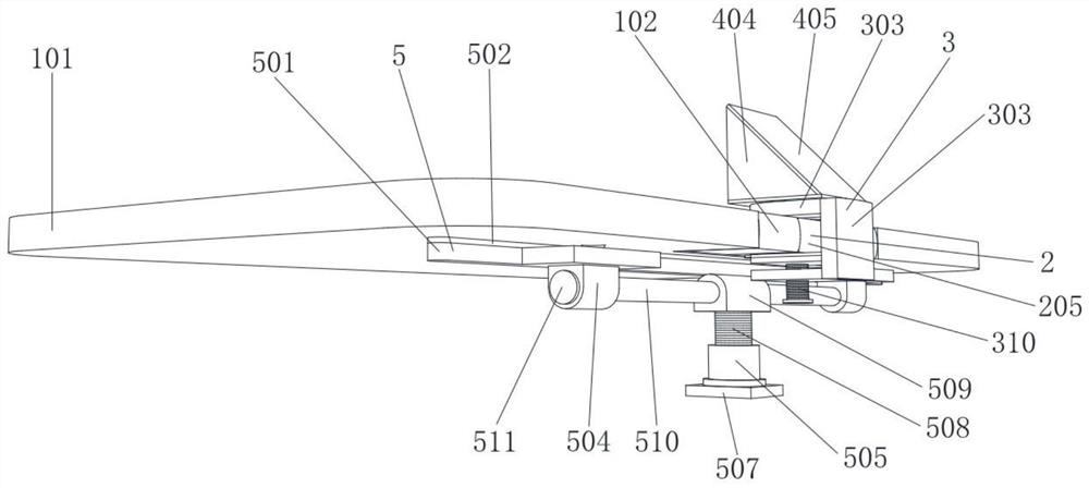
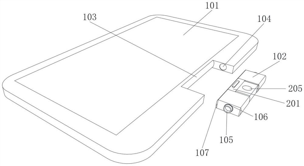
[0032] Example 1, please refer to figure 1 , figure 2 , image 3 , Figure 4 , Figure 5 , Image 6 , Figure 7 with Figure 8 , an educational tablet computer with an adjustable camera angle, comprising a tablet computer 101 and a rectangular box 102, an arc rod-103 is installed on the tablet computer 101, a circular through-hole 104 is opened on the left and right sides of the inner wall of the tablet computer 101, and a rectangular box 102 is provided. Ring one 105 is installed on the right side of box 102, and ring two 106 is installed on the ring one 105, and arc bar two 107 is all installed on the front and back sides of rectangular box 102, and chute block 108 is installed on the left side of rectangular box 102, and rectangular box 102 left side is equipped with chute block 108, and The box 102 is installed on the tablet computer 101 through the ring one 105. The front end of the tablet computer 101 is provided with a camera mechanism 2 that can be adjusted up a...
Embodiment 2
[0034] Example 2, please refer to figure 1 , figure 2 , Figure 9 with Figure 10 , on the basis of Embodiment 1, the camera 205 is provided with a connection and clamping mechanism 3 for clamping the camera 205. The connection and clamping mechanism 3 includes an arc plate 301, a square plate 305 and a bolt 310, and the back side of the arc plate 301 is provided with T-shaped hole 302, semicircular plate 303 and square plate 2 309 are fixedly connected to the back side of arc plate 301, gasket 1 304 is installed on the lower side of semicircular plate 303, slider 2 306 is installed on the front side of square plate 305, and square plate 1 Gasket 2 307 is installed on the upper side of 305, and bearing 1 308 is installed on the lower side of square plate 1 305. Threaded through hole 311 is arranged, and bolt 310 is installed on square plate two 309 by threaded through hole 311, and square plate two 309 upper side is equipped with spring 312, and square plate two 309 and sq...
Embodiment 3
[0036] Embodiment three, please refer to figure 1 , figure 2 , Figure 9 , Figure 10 with Figure 11 , on the basis of the second embodiment, the upper side of the semicircular plate 303 is provided with a 313, the semicircular plate 303 is provided with a reflection mechanism 4, the reflection mechanism 4 includes a square plate three 401, and the lower side of the square plate three 401 is equipped with a ring five 402, Ring 6 403 is installed on the lower side of ring 5 402, square plate 3 401 and semi-circular plate 303 are clamped and rotated through ring 6 403 and 313, and square plate 3 401 is equipped with triangular plate 404, reflector 405 and glass block 406 , the structural shape of the reflection mechanism 4 is a triangle, the square plate three 401 is located directly above the camera 205 , and the included angle between the reflection plate 405 and the square plate three 401 is 45 degrees.
[0037] When in use, the user inserts the reflection mechanism 4 i...
PUM
 Abstract
Description
Claims
Application Information
 - R&D
- Intellectual Property
- Life Sciences
- Materials
- Tech Scout
- Unparalleled Data Quality
- Higher Quality Content
- 60% Fewer Hallucinations
Browse by: Latest US Patents, China's latest patents, Technical Efficacy Thesaurus, Application Domain, Technology Topic, Popular Technical Reports.
© 2025 PatSnap. All rights reserved.Legal|Privacy policy|Modern Slavery Act Transparency Statement|Sitemap|About US| Contact US: help@patsnap.com


