Load maintaining sheet type multi-way valve

A load holding and multi-way valve technology, applied in the hydraulic field, can solve problems such as oil leakage and arm drop, and achieve the effect of ensuring sealing performance, good sealing effect, and preventing arm drop

Pending Publication Date: 2021-08-03
JIANGSU HENGLI HYDRAULIC +1
View PDF1 Cites 1 Cited by
  • Summary
  • Abstract
  • Description
  • Claims
  • Application Information

AI Technical Summary

Problems solved by technology

[0003] In order to solve the problem of the multi-way valve existing in the prior art that the oil leaks when the spool is in the neutral position for load holding and causes the arm to drop, the present invention provides a load holding multi-way valve that prevents oil leakage during load holding

Method used


Image

  • Load maintaining sheet type multi-way valve
  • Load maintaining sheet type multi-way valve
  • Load maintaining sheet type multi-way valve

Examples


Embodiment 1

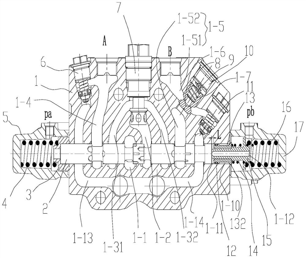
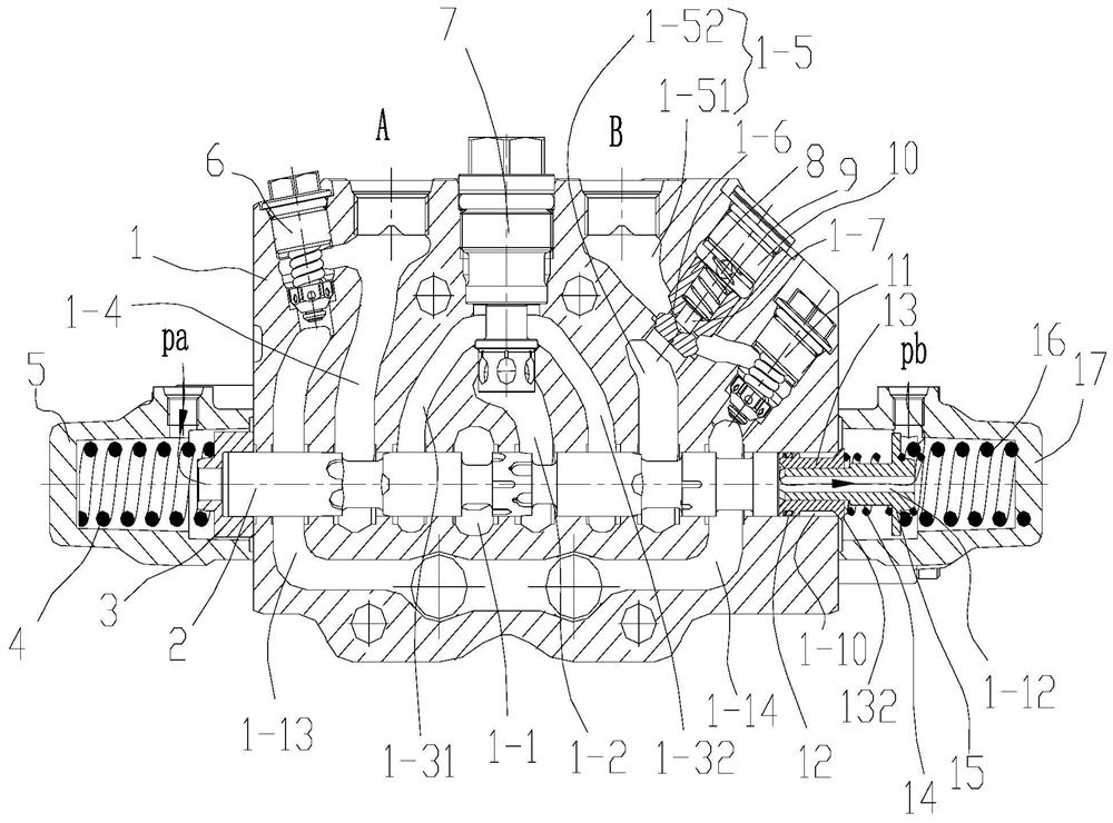
[0061] In the present invention, the valve sleeve 13 is slidingly connected with the ejector rod 15, and the ejector rod 15 is provided with a step for supporting the valve sleeve 13 to the direction of the valve core 2, and the groove on the valve sleeve 13 extends to the sealing structure, and when the ejector rod 15 against the valve sleeve 13, and when the sealing structure of the valve sleeve 13 cooperates with the valve body 1, the end of the ejector rod 15 close to the valve core 2 exceeds the end of the valve sleeve 13 close to the valve core 2 by a distance L, where L can be equal to Figure 8 2x in the middle, so that the valve core 2 first contacts with the ejector rod 15 and then contacts with the valve sleeve 13. There is a device on the valve body 1 or between the valve sleeve 13 and the ejector rod 15 for adjusting the valve before the valve core 2 contacts with the valve sleeve 13. Cover 13 carries out the position-limiting structure of position-limiting.

Embodiment 2

[0063] The valve sleeve 13 is slidingly connected with the ejector rod 15, and the ejector rod 15 is provided with a step for supporting the valve sleeve 13 to the direction of the valve core 2. When body 1 cooperates, such as Figure 11 , the end of the valve sleeve 13 close to the valve core 2 exceeds the end of the ejector rod 15 close to the valve core 2 or both are flush, and the distance between the groove on the valve sleeve 13 and the sealing structure is L, and the valve sleeve 13 is in the groove The size of the outer circle between the sealing structure matches the valve core hole and the valve sleeve 13 can slide in the valve core hole. This embodiment can solve the problem of oil leakage when the valve core 2 is in the neutral position. When the core 2 pushes the valve sleeve 13 to move to the pilot oil chamber, after the sealing structure is separated from the valve body 1, a little oil will flow from the gap between the valve sleeve 13 and the valve core hole to...

Embodiment 3

[0065] The push rod 15 is integrally formed or fixedly connected with the valve sleeve 13, and there is a distance L between the groove of the valve sleeve 13 and the raised portion 132, where L can be equal to Figure 8 2x in , the principle and effect of this embodiment are similar to those of Embodiment 2, and will not be repeated here.

[0066] The limiting structure in Embodiment 1 and Embodiment 2 can be in the form of a movable gear rod or stopper, etc., the gear rod or stopper blocks the valve sleeve 13 before the valve core 2 contacts the valve sleeve 13, the gear rod or the stopper Loosen the valve sleeve 13 after the valve core 2 is in contact with the valve sleeve 13 . In the present invention, the limiting structure is a second elastic element arranged between the valve sleeve 13 and the push rod 15 . The second elastic element is the second spring 14 .

[0067] A first flow passage 1-6 is provided between the cavity 1-7 of the check valve 8 and the second worki...


PUM


Abstract

The invention relates to the technical field of hydraulic pressure, in particular to a load maintaining sheet type multi-way valve which comprises a valve body, a valve element, a one-way valve hole, at least one pilot oil cavity, a middle body and an on-off mechanism. A valve element hole, working oil cavities, an oil inlet cavity and an oil return cavity are formed in the valve body, the working oil cavities, the oil inlet cavity and the oil return cavity are communicated with the valve element hole, the oil inlet cavity is connected with an oil inlet, and the oil return cavity is connected with an oil return opening; the valve element is arranged in the valve element hole and used for oil way conversion; the one-way valve hole is communicated with one working oil cavity, a one-way valve is arranged in the one-way valve hole, and a cavity communicated with the corresponding working oil cavity is formed in the one-way valve; the middle body is provided with a pilot channel and a middle channel, the pilot channel is used for communicating the pilot oil cavity with the valve element hole to push the valve element to move, and the middle channel is communicated with a cavity body of the one-way valve; and the on-off mechanism is used for communicating or disconnecting the middle channel and the pilot oil cavity. According to the load maintaining sheet type multi-way valve, oil in the cavity body of the one-way valve communicates with the middle channel at the end of the valve element hole, so that sealing between the cavity body of the one-way valve and the valve element hole is conveniently achieved.

Description

technical field [0001] The invention relates to the technical field of hydraulic pressure, in particular to a load holding multi-way valve. Background technique [0002] In the prior art, the on-off of the oil circuit is controlled by a one-way valve in the multi-way valve. For example, the patent No. CN207568965U, when the control valve is in the neutral position, due to the gravity of the working device, the actuator (oil cylinder) produces a certain The pressure is transmitted to the main spool through the one-way valve and the pipeline, because the main spool is set in the spool hole by the slideway, so there is always a gap between the main spool and the spool hole, resulting in a certain Leakage, resulting in arm drop phenomenon. Contents of the invention [0003] In order to solve the problem existing in the prior art that the multi-way valve is in the neutral position for load holding and oil leakage leads to arm drop, the present invention provides a load holding...

Claims


Application Information

Patent Timeline
Patent Type & Authority Applications(China)
IPC IPC(8): F15B11/05F15B13/02F16K15/18F16K11/07F16K31/36F16K17/168
CPCF15B11/05F15B13/02F15B13/026F16K11/07F16K15/18F16K17/168F16K31/36
Inventor 汪立平高雪涛刘红光杨泽贺韩日升
Owner JIANGSU HENGLI HYDRAULIC
Why Eureka
Try Eureka