Catenary power supply device and power supply method for EMU insulation
A technology of power supply device and catenary, which is applied to AC networks with the same frequency from different sources, power lines, vehicle components, etc., to achieve the effect of saving project investment and operating costs
- Summary
- Abstract
- Description
- Claims
- Application Information
AI Technical Summary
Problems solved by technology
Method used
Image
Examples
Embodiment 1
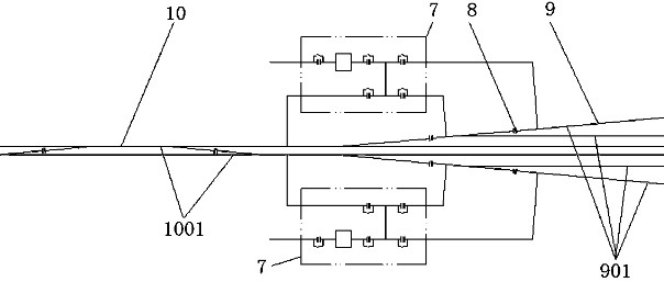
[0051] This embodiment introduces the specific application of the catenary power supply device and method for thermal insulation of EMUs in stations, including main line catenary 10, arrival and departure catenary 9 and two catenary for thermal insulation of EMUs The power supply device 7, the main catenary 10 contains two main catenary power supply partitions 1001, and the catenary 9 to the distribution line contains a plurality of catenary power supply partitions 901 to the distribution line, and the voltage of the industrial power supply is 10kV;
[0052] The input terminal of the first isolating switch 2 of the catenary power supply device 7 for the thermal insulation of the EMU is connected to the 10kV power supply, and the third isolation of the catenary power supply device 7 for the thermal insulation of the EMU is first described. The input end of the switch 5 is connected to the first positive line catenary power supply partition 1001;
[0053] The input terminal of t...
Embodiment 2
[0059] The main difference between this embodiment and Embodiment 1 is that the two catenary power supply devices 7 used for thermal insulation of EMUs in Embodiment 1 can be combined into one, that is, there is only one catenary power supply device for thermal insulation of EMUs 7. Wherein the fourth isolating switch 6 is changed from 2 to 4, and the traction power supply is introduced from 2 positive line catenary to 1 positive line catenary.
[0060] The input terminal of the first isolating switch 2 of the catenary power supply device 7 used for the thermal insulation of the EMU is connected to a 10kV power supply, and the input terminal of the third isolating switch 5 of the catenary power supply device 7 used for the thermal insulation of the EMU is connected to the The first positive catenary power supply sub-area 1001 is connected;
[0061] The output end of the transmission branch line 13 of the catenary power supply device 7 used for the thermal insulation of the EM...
Embodiment 3
[0063] The main difference between this embodiment and Embodiment 1 is that this embodiment is the application of the catenary power supply device 7 for thermal insulation of EMUs in a parking lot.
[0064] Specifically, it includes the catenary 12 of the parking lot access line, the catenary line 11 of the car storage line, and two catenary power supply devices 7 for the heat preservation of the EMU, and the catenary 12 of the parking lot access line contains 2 parking lot access lines. The catenary power supply partition 1201, the catenary 11 of the car storage line contains 2 catenary power supply partitions 1101 of the car storage line; the catenary 12 voltage of the parking lot entrance and exit line is 25kV;
[0065] The input terminal of the first isolating switch 2 of the first catenary power supply device 7 used for EMU insulation is connected to the 10kV power supply, and the third isolating switch 5 of the first catenary power supply device 7 used for EMU insulation ...
PUM
 Abstract
Description
Claims
Application Information
 - R&D
- Intellectual Property
- Life Sciences
- Materials
- Tech Scout
- Unparalleled Data Quality
- Higher Quality Content
- 60% Fewer Hallucinations
Browse by: Latest US Patents, China's latest patents, Technical Efficacy Thesaurus, Application Domain, Technology Topic, Popular Technical Reports.
© 2025 PatSnap. All rights reserved.Legal|Privacy policy|Modern Slavery Act Transparency Statement|Sitemap|About US| Contact US: help@patsnap.com


