
Initial position identification method for three-phase permanent magnet synchronous motor

A permanent magnet synchronous motor, initial position technology, applied in the direction of control generator, motor control, motor generator control, etc., can solve the problems of high frequency noise, affecting accuracy, movement and so on

Pending Publication Date: 2021-07-30
杭州微秦科技有限公司
View PDF2 Cites 0 Cited by
  • Summary
  • Abstract
  • Description
  • Claims
  • Application Information

AI Technical Summary

Problems solved by technology

However, the initial position identification of three-phase permanent magnet synchronous motors and brushless DC motors without speed or position sensors has always been a difficult point in academia and industry
[0003] Generally speaking, the methods for judging the initial position of the motor in the prior art are mainly divided into two categories: the first category is to inject a pulse sequence at the moment of starting, according to the magnetic circuit saturation characteristics of the permanent magnet motor and the reluctance inconsistency of the orthogonal and direct axes , and identify the initial position of the motor; for example, Chinese patent document CN110932636A discloses a method and system for identifying the initial position of a permanent magnet synchronous motor. Oscillation angle identification and negative oscillation angle identification, the first pulse array and the second pulse array are obtained respectively, the rationality test and the mean value regression algorithm calculation are carried out on the first pulse array and the second pulse array, and the initial position of the motor zero position is obtained. The initial position of the zero position of the motor is detected; although the advantage of injecting pulse sequences is that the identification time is short and relatively accurate, the motor must be stationary during the entire identification process, and a small disturbance will affect the final position accuracy, especially the magnetic field polarity (Judgment of N / S pole) itself is carried out by the saturation of the magnetic circuit, which is very disturbed by the motor disturbance and makes a misjudgment, and there will be an obvious noise during the identification process, and the injected pulse series itself is easy to move the position of the motor
[0004] The second type is the high-frequency injection scheme. According to the impedance characteristics of the motor, the influence of the resistance becomes smaller and smaller at high frequencies, and the difference in the inductance characteristics of the motor will appear very prominent; the advantage of high-frequency injection is that it can be identified online, but the identification The time is long, the efficiency is low, the accuracy is poor, and it will generate high-frequency noise, and the starting torque is also small. A large part of the injected signal is destined to identify the position and cannot do work
[0005] In addition, there are also some methods for detecting the back EMF. For example, the Chinese patent document CN101425769A discloses a method for quickly detecting the rotor position of a three-phase permanent magnet synchronous motor without a position sensor. After conversion, the absolute value of the minimum opposite potential value is interpolated and compared to determine the closest point corresponding to the rotor position in the rotor position curve; however, this method needs to start the motor, which is no longer the initial position identification category of the three-phase permanent magnet synchronous motor.

Method used


Image

  • Initial position identification method for three-phase permanent magnet synchronous motor
  • Initial position identification method for three-phase permanent magnet synchronous motor

Examples


Embodiment Construction

[0024] The specific implementation of the present invention will be described in detail below in conjunction with the accompanying drawings. It should be pointed out that the embodiment is only a specific elaboration of the invention and should not be regarded as limiting the invention. The purpose of the embodiment is to make those skilled in the art better To better understand and reproduce the technical solution of the present invention, the protection scope of the present invention should still be defined by the claims.

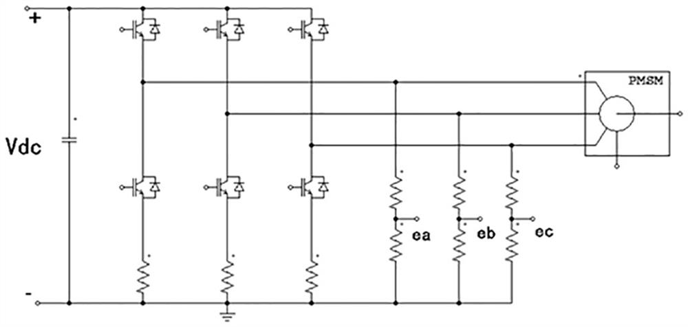
[0025] Such as figure 1 As shown, the PMSM in the figure represents a permanent magnet synchronous motor.

[0026] The invention provides a method for identifying the initial position of a permanent magnet synchronous motor. In the method, at least one of the three phases of the three-phase permanent magnet synchronous motor is connected to a back EMF detection circuit, and the feedback value of the back EMF detection circuit is used to judge The rotatio...


PUM


Abstract

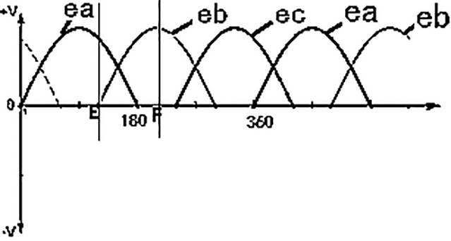
The invention aims to provide an initial position identification method for a three-phase permanent magnet synchronous motor. According to the method, at least one of three phases of the three-phase permanent magnet synchronous motor is connected with a counter electromotive force detection circuit, and the rotation angle of the three-phase permanent magnet synchronous motor is judged according to a feedback value of the counter electromotive force detection circuit, so that the initial position of the three-phase permanent magnet synchronous motor is identified. The back electromotive force is detected when a switch is turned off, the accurate position of the motor can be quickly and effectively found, and various defects caused by conventional injection pulses or high-frequency signals in the industry at present can be completely overcome.

Description

technical field [0001] The invention relates to the field of permanent magnet synchronous motor control, in particular to a method for identifying the initial position of the motor. Background technique [0002] The permanent magnet synchronous motor without speed or position sensor is a hot spot in the research of permanent magnet synchronous motor at present, and it is also one of the development trends of permanent magnet synchronous motor drive system, which has potential competitive advantages. However, the initial position identification of three-phase permanent magnet synchronous motors and brushless DC motors without speed or position sensors has always been a difficult point in academia and industry. [0003] Generally speaking, the methods for judging the initial position of the motor in the prior art are mainly divided into two categories: the first category is to inject a pulse sequence at the moment of starting, according to the magnetic circuit saturation chara...

Claims


Application Information

Patent Timeline
Patent Type & Authority Applications(China)
IPC IPC(8): H02P21/32H02P21/18H02P25/022
CPCH02P25/022H02P2207/05H02P21/18H02P21/32
Inventor 秦岭
Owner 杭州微秦科技有限公司
Learn More