
3D model lofting method based on computer geometric migration algorithm

A geometric offset and computer technology, applied in the field of 3D model lofting based on the computer geometric offset algorithm, can solve the problem of high cost of optimization processing

Active Publication Date: 2021-07-30
JIANGSU UNIV
View PDF6 Cites 1 Cited by
  • Summary
  • Abstract
  • Description
  • Claims
  • Application Information

AI Technical Summary

Problems solved by technology

This optimization is often expensive

Method used


Image

  • 3D model lofting method based on computer geometric migration algorithm
  • 3D model lofting method based on computer geometric migration algorithm
  • 3D model lofting method based on computer geometric migration algorithm

Examples


Embodiment Construction

[0085] The technical solution of the present invention will be further described below in conjunction with the accompanying drawings.

[0086] The 3D model lofting method based on the computer geometric offset algorithm of the present invention comprises the following steps:

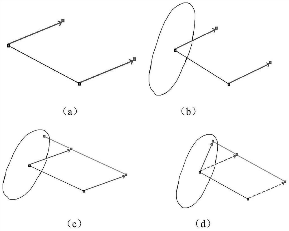
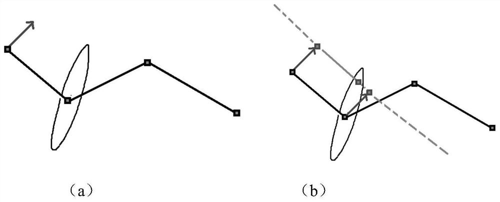
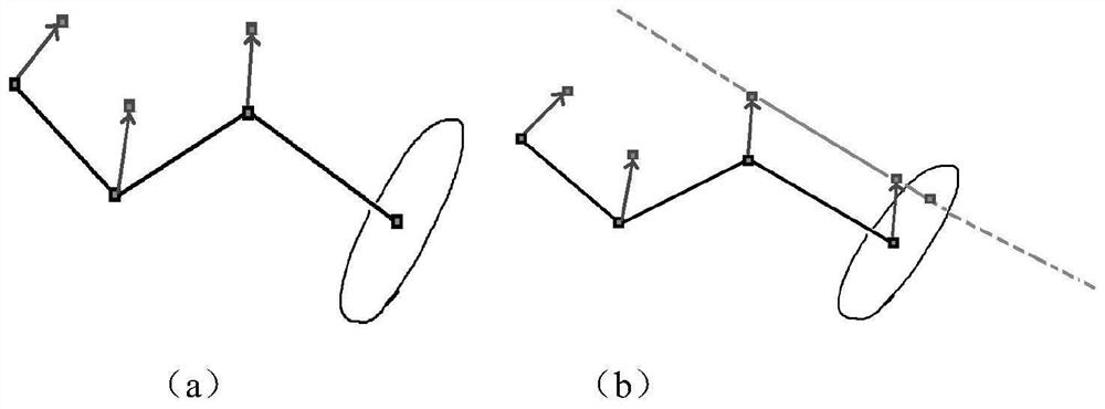
[0087] (1) Obtain a cross-sectional polyline with M vertices and a polyline to be offset according to hardware device input / interaction with other software;

[0088] (2) Obtain the initial offset vector group whose length is equal to the number of vertices M according to the first vertex of the cross-section polyline and the polyline to be offset. The specific implementation of step (2) is as follows:

[0089] (21) statement counter k=0, assuming that the coordinate of the first vertex of polyline to be offset is p0;

[0090] (22) Obtain the k+1 vertex coordinate p of the cross-sectional polyline;

[0091] (23) Assign the k+1th element of the offset vector group to vector p-p0;

[0092] (24) If k


PUM


Abstract

The invention discloses a 3D model lofting method based on a computer geometric migration algorithm, and the method comprises the following steps: (1) obtaining a cross section broken line with the vertex number of M and a broken line to be migrated according to hardware equipment input / interaction with other software; (2) obtaining an initial offset vector group of which the length is equal to the number M of vertexes according to the cross section broken line and the first vertex of the broken line to be offset; (3) adopting an offset algorithm to respectively obtain M offset broken lines corresponding to the M vertexes in the cross section broken lines, and forming a broken line group by the M offset broken lines; (4) adopting the offset broken line and the broken line to be offset to generate triangular patch data; and (5) performing meshing by adopting the triangular patch data to generate a 3D model. According to the method, the overlapping problem caused by input broken line external expansion operation is solved, and the calculation amount is reduced; the method not only can be used for generating the lofting grid, but also can be used as any grid generation calculation scheme, so that the generated 3D grid or 2D grid is more excellent.

Description

technical field [0001] The invention relates to the fields of computer graphics, 3D modeling and game animation, in particular to a 3D model lofting method based on a computer geometric offset algorithm. Background technique [0002] Common animation generation methods include skin animation and lofting technology. [0003] The two core pieces of data in skinned animation are bones and models. Skeleton data describes the parent-child relationship, so as to facilitate the subsequent freeze frame and animation production; model data describes a static object that is expected to drive it. The artist will deploy everything in the model data, including the image of the object described by the model, the number of bones driving the model, and the description of the driving effect. The animation software generates the position sequence of the skeleton of the model and interpolates it to obtain a coherent skeleton animation. Skeletal animation will use bone binding and deformatio...

Claims


Application Information

Patent Timeline
Patent Type & Authority Applications(China)
IPC IPC(8): G06T11/20
CPCG06T11/203
Inventor 刘梦祈赵岩
Owner JIANGSU UNIV
Learn More