


Quick Research
Generate reliable direction feasibility study reports for your R&D in just a few steps.

Technical Q&A
Discover and master advanced knowledge NOW. Basics, ideas, possibilities, all at once.

Find Solutions
As an expert in R&D theories, this can generate solutions to your technical problems instantly.

Evaluate Feasibility
Analyze your overall solution with one click, know your potential R&D risks in advance.

Monitor Landscape
Get weekly tech updates, stay abreast of the latest tech innovations and key insights.
Power plant flue ash removal device
A technology for flue dust cleaning and power plants, which is applied in the direction of solid residue removal, combustion product treatment, combustion methods, etc., and can solve problems such as poor overall effect, large emissions, and affecting the normal operation of denitrification devices
- Summary
- Abstract
- Description
- Claims
- Application Information
AI Technical Summary
Problems solved by technology
Method used
Image

Examples
Embodiment 1
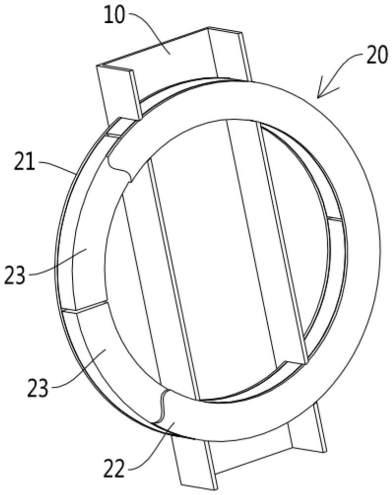
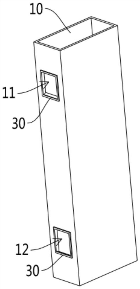
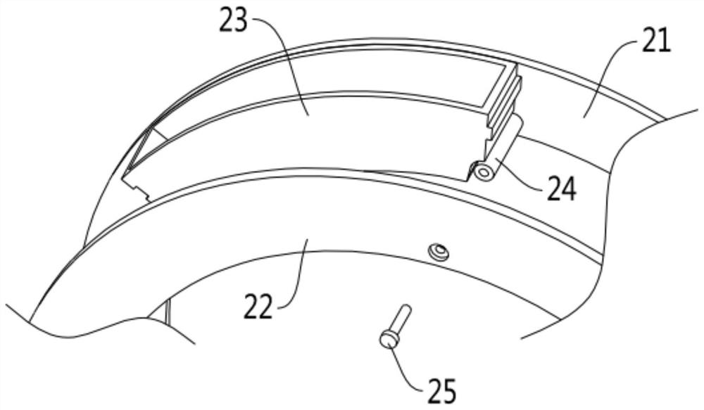
[0024] see Figures 1 to 4 As shown, a power plant flue dust removal device involved in this embodiment includes a flue 10 and an ash removal assembly 20, the ash removal assembly 20 is in the shape of a ring, and the flue 10 is provided with a The assembly 20 passes through and rotates in the first adjustment channel 11 and the second adjustment channel 12. The cleaning assembly 20 includes a first ring piece 21 and a second ring piece 22. The first ring Between the ring piece 21 and the second ring piece 22 are provided several filter units 23 arranged along the circumferential direction of the cleaning assembly 20 .
[0025] Further, the filter unit 23 includes a housing 231 filled with a filter element (not shown in the figure), and the housing 231 is provided with a filter port for the filter element to contact with the smoke in the flue 10 232.
[0026] Further, the filter element can be taken out from the casing 231 through the filter port 232 .
[0027] Further, the...
Embodiment 2
[0034] see Figures 1 to 4 As shown, the power plant flue dust cleaning device involved in this embodiment is further set up on the basis of Embodiment 1 so that two adjacent filter units 23 are connected end to end.
[0035] Further, one end of the filter unit 23 has a protrusion 233 , and the other end has a groove 234 matching the protrusion 233 .
[0036] Further, the filter units 23 are distributed between the first annular piece 21 and the second annular piece 22 in an angular array at equal intervals.
[0037] Further, the number of the filtering units 23 is six.
[0038] In this embodiment, by closely arranging the filter units 23 connected end-to-end between the first annular piece 21 and the second annular piece 22, the arrangement number of the filter units 23 is maximized and the space utilization rate is improved; at the same time It is also ensured that the dust-cleaning assembly 20 cut into the flue 10 section is covered with filter units 23 to achieve the bes...
Embodiment 3
[0041] see Figures 1 to 4 As shown, a power plant flue dust cleaning device involved in this embodiment, on the basis of Embodiments 1 and 2, is further set as, the passage openings of the first regulating passage 11 and the second regulating passage 12 Sealing rings 30 are respectively provided.
[0042] In this embodiment, the sealing ring 30 is provided through the channel opening to prevent the smoke and dust from floating out of the gap during the circumferential rotation of the dust cleaning assembly 20 relative to the flue 10, thereby improving the sealing performance.
[0043] The flue dust cleaning device of the power plant involved in the present invention rotates the ring-shaped dust cleaning assembly relative to the flue, so that the filter units located in the flue are switched, cut into the unused filter unit, and cut out the used filter unit. The filter unit can be replaced outside the flue without stopping the operation, and it is safe and reliable to use. B...
PUM
 Abstract
Description
Claims
Application Information
 - R&D Engineer
- R&D Manager
- IP Professional
- Industry Leading Data Capabilities
- Powerful AI technology
- Patent DNA Extraction
Browse by: Latest US Patents, China's latest patents, Technical Efficacy Thesaurus, Application Domain, Technology Topic, Popular Technical Reports.
© 2024 PatSnap. All rights reserved.Legal|Privacy policy|Modern Slavery Act Transparency Statement|Sitemap|About US| Contact US: help@patsnap.com