Control device for paper printing or film laminating

A control device and lamination technology, which can be applied to general parts of printing machinery, printing, printing machines, etc., and can solve problems such as being easily touched by mistake.

Inactive Publication Date: 2021-07-30
武汉鸿印社科技有限公司
View PDF7 Cites 0 Cited by
  • Summary
  • Abstract
  • Description
  • Claims
  • Application Information

AI Technical Summary

Problems solved by technology

[0004] Aiming at the deficiencies of the prior art, the present invention provides a control device for paper printing or lamination, which has the advantages of preventing false touches, etc., and solves the problem that traditional cases are directly exposed and easy to be mistakenly touched

Method used


Image

  • Control device for paper printing or film laminating
  • Control device for paper printing or film laminating
  • Control device for paper printing or film laminating

Examples


Embodiment 1

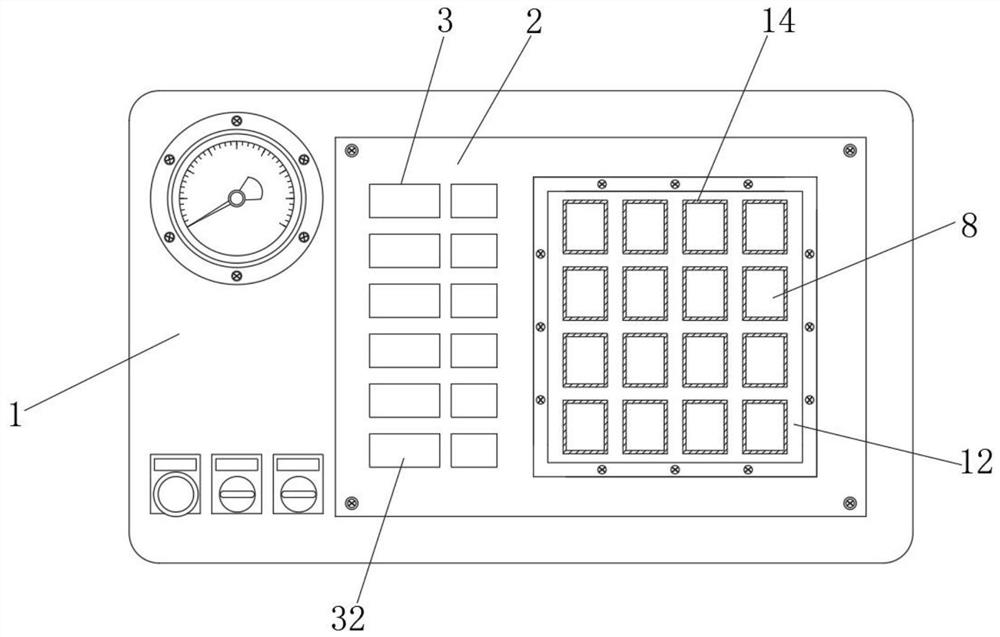
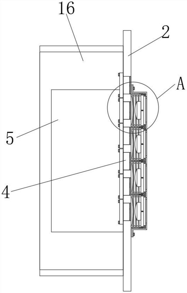
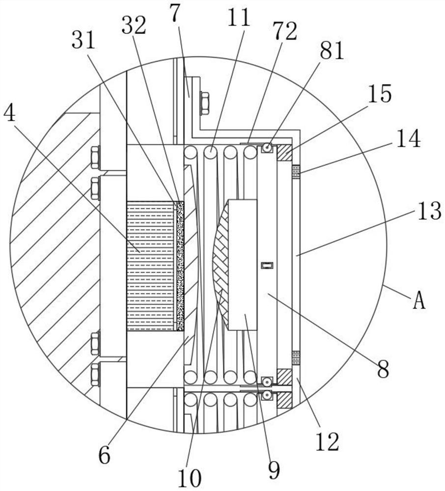
[0036] Example 1, see Figure 1-6, the control device for paper printing or laminating of the present invention includes a control cabinet 1 and a control device, the control device includes a controller mounting plate 2, an LED digital tube 4 and a digital input device 5, and the controller mounting plate 2 is fixed by screws Connected to the front of the control box 1, the front of the controller mounting plate 2 and near the left side are provided with a digital tube installation slot 3 for installing the LED digital tube 4 at equal distances along the vertical direction, and the LED digital tube 4 is installed from the digital tube installation slot 3 is inserted in the back and fixed with the back of the controller mounting plate 2 by screws, and the digital input device 5 is fixedly connected to the back of the controller mounting plate 2 and near the right side by screws, and the front of the controller mounting plate 2 is connected to the digital input device Button 6 ...

Embodiment 2

[0042] Embodiment 2: Different from Embodiment 1, the inside of the through hole 13 is glued and fixedly connected with a silicone gasket 14. The front view of the silicone gasket 14 is rectangular, which can prevent people's fingers from colliding with the inside of the through hole 13. played a protective role.

Embodiment 3

[0043] Embodiment 3: Different from Embodiment 1, a fixed frame 31 is integrally formed on the inside of the nixie tube installation groove 3 and near the front, and the front of the fixed frame 31 is glued and fixed with a transparent glass 32, and the front of the transparent glass 32 is connected to the digital The fronts of the tube mounting groove 3 are on the same horizontal plane, which can protect the LED digital tube 4 while not affecting people's observation of the numbers displayed by the LED digital tube 4 .

[0044] Working principle: When the staff needs to operate the button 6, they only need to press the pressure plate 8 with the corresponding text mark with their fingers. After the pressure plate 8 is under pressure, the return spring 11 will be compressed until the silicone protrusion 10 on the pressure plate 8 presses the button 6 times, at this time, the staff can confirm the success of the input by observing the changes in the numbers displayed on the LED d...


PUM


Abstract

The invention relates to the technical field of controllers for film laminating machines, and particularly discloses a control device for paper printing or film laminating. The control device comprises a control case and a control device; the control device comprises a controller mounting plate, an LED nixie tube and a digital input unit; the digital input unit is fixedly connected to the position, close to the right side, on the back face of the controller mounting plate through screws; buttons are arranged at the position, corresponding to the digital input unit, on the front face of the controller mounting plate; an inner mounting frame is detachably fixed to the position, corresponding to the center of the buttons, on the front face of the controller mounting plate; through grooves are formed in the position, corresponding to the buttons, on the front face of the inner mounting frame; pressing plates are slidably connected into the through grooves; and an outer mounting frame used for limiting the positions of the pressing plates is fixedly inserted into the front face of the inner mounting frame. All the buttons can be wrapped by a mounting frame, the buttons need to be pressed through the pressing plates, and the pressing plates are independently arranged in the through grooves, so that mistaken touch is avoided.

Description

technical field [0001] The invention relates to the technical field of controllers for laminating machines, in particular to a control device for paper printing or laminating. Background technique [0002] The laminating machine is a special equipment for paper and film. The laminating machine includes three functions of gluing, drying and hot pressing. It has a wide range of applications and stable and reliable processing performance. It is widely used in the paper industry. Equipment, the current laminating machine is operated through the controller, and people only need to input the corresponding parameters and instructions through the controller, so that the laminating machine can laminate the paper. [0003] The buttons on the current controller are roughly in a plane, and the staff can easily touch other buttons by mistake when operating the buttons, and the current buttons will input instructions to the controller when the buttons are slightly squeezed, which is easy ...

Claims


Application Information

Patent Timeline
IPC IPC(8): B41F23/08B41F33/16
CPCB41F23/08B41F33/16
Inventor 周谊涛张单韩雄文舒正伟田以红邹艳莲
Owner 武汉鸿印社科技有限公司
Why Eureka
Try Eureka