DC current detection system based on intelligent electric power and detection method thereof

A DC current and detection system technology, applied in the direction of only measuring current, measuring current/voltage, components of electrical measuring instruments, etc., can solve the problems of unusable circuits, low degree of intelligence, inconvenient to connect electrical appliances for continuous use, etc. To achieve the effect of convenient extraction work

Inactive Publication Date: 2021-07-27
曹海波
View PDF0 Cites 0 Cited by
  • Summary
  • Abstract
  • Description
  • Claims
  • Application Information

AI Technical Summary

Problems solved by technology

[0004] The existing DC detection needs to be carried out by using an ammeter, and the ammeter needs to be connected in series inside the circuit for measurement during the detection, so that the circuit needs to be disconnected when it is merged, and then the circuit is started after the connection, causing the circuit to be in a certain period of time. Unusable, inconvenient for continuous use of connected electrical appliances. At the same time, the specific data needs to be manually recorded after the data measurement is completed, and the detected data cannot be stored, which leads to the need to use a large number of other equipment for subsequent calculation and recording work, and the degree of intelligence is low. , so there is an urgent need for a system to solve the above problems

Method used


Image

  • DC current detection system based on intelligent electric power and detection method thereof
  • DC current detection system based on intelligent electric power and detection method thereof
  • DC current detection system based on intelligent electric power and detection method thereof

Examples


Embodiment Construction

[0031] The following will clearly and completely describe the technical solutions in the embodiments of the present invention with reference to the accompanying drawings in the embodiments of the present invention. Obviously, the described embodiments are only some, not all, embodiments of the present invention. Based on the embodiments of the present invention, all other embodiments obtained by persons of ordinary skill in the art without making creative efforts belong to the protection scope of the present invention.

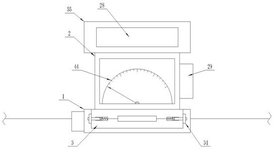
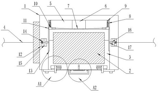
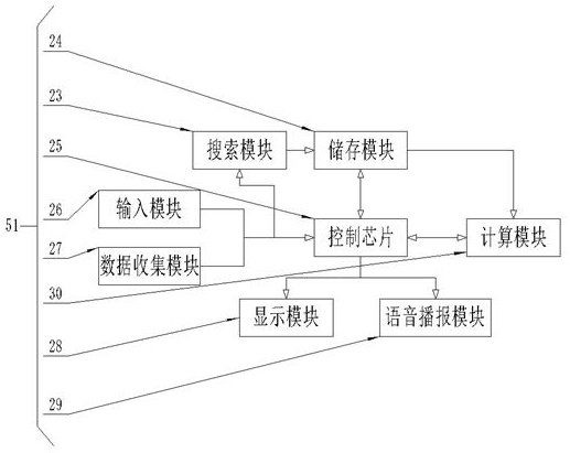
[0032] see Figure 1-7 , the present invention provides a technical solution: a DC current detection system based on smart electric power, including a fixed seat 1, an ammeter body 2 and a base 3, and a housing 55 is fixedly installed on the upper end of the ammeter body 2, and the housing A recording system 51 is set inside the body 55, an indicator plate 44 is set at the front end of the ammeter main body 2, the first power cord 4 is fixedly connected to the...


PUM


Abstract

The invention discloses a direct current detection system based on intelligent electric power and a detection method thereof. The system comprises a fixing base, an ammeter body and a base, a shell is fixedly installed at the upper end of the ammeter body, a recording system is arranged in the shell, and an indicating dial is arranged at the front end of the ammeter body; first power lines are fixedly connected to the two side ends of the fixing seat, a protection mechanism is arranged at the left side end of the fixing seat, a placement groove is formed in the fixing seat, and a base is movably clamped in the placement groove. When the system is normally used, the horizontal rod is matched with mercury to conduct electricity, if connection detection is carried out, passing current is too large when electrical equipment is short-circuited, the horizontal rod is heated to heat and expand the mercury, and therefore the conductivity of the mercury is reduced, and the situation that the detected current meter body is damaged due to sudden too large current is prevented; and the connected electrical equipment can be effectively protected.

Description

technical field [0001] The invention relates to the field of current detection equipment, in particular to a DC current detection system and a detection method based on smart electric power. Background technique [0002] The current whose direction remains unchanged is called direct current, commonly known as direct current. That is, the electric quantity passing through the cross-section of the conductor in unit time is equal, which is called steady current or constant current, referred to as direct current, denoted as DC or dc, and direct current is represented by capital letter I. [0003] Direct current is common in many extra-low and low-voltage devices, especially those powered by batteries that can only generate direct current. It is also possible to use a solar power system, because solar cells can only produce direct current. Most auto parts use direct current. [0004] The existing DC detection needs to be carried out by using an ammeter, and the ammeter needs t...

Claims


Application Information

Patent Timeline
Patent Type & Authority Applications(China)
IPC IPC(8): G01R19/00G01R1/04
CPCG01R1/0408G01R19/0092
Inventor 曹海波
Owner 曹海波
Why Eureka
Try Eureka