Low-cycle fatigue composite test device

A composite test, low cycle fatigue technology, used in measuring devices, mechanical parts testing, machine/structural parts testing, etc. It can solve the problems of insufficient test power and efficiency, high cost, and inconvenient installation, and achieve easy batch production. The effect of experiment, convenient operation and simple structure

Inactive Publication Date: 2021-07-27
HARBIN INST OF TECH
View PDF0 Cites 1 Cited by
  • Summary
  • Abstract
  • Description
  • Claims
  • Application Information

AI Technical Summary

Problems solved by technology

However, the installation of the above blade fatigue test device is not convenient enough, the cost is high, and the test power and efficiency are insufficient, the measurement results are not accurate enough, and the adaptability is not good.

Method used


Image

  • Low-cycle fatigue composite test device
  • Low-cycle fatigue composite test device
  • Low-cycle fatigue composite test device

Examples


Embodiment 1

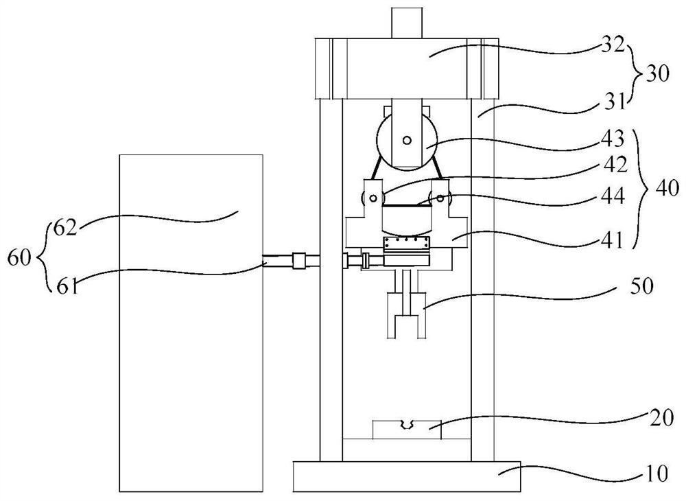
[0052] Such as Figure 4 As shown, in one embodiment of the present application, the horizontal moving device 40 includes: a sliding seat 41 , a plurality of rollers 42 , a fixed pulley 43 and a connecting belt 44 .

[0053] The sliding seat 41 is connected with a load applying device 60 .

[0054] A plurality of roller shafts 42 are arranged on the sliding seat 41 and can rotate relative to the sliding seat 41 , and axes of the plurality of roller shafts 42 are located in the same parallel plane. In a specific embodiment of the present application, two roller shafts 42 are arranged on the sliding seat 41 , and there is an interval between the two roller shafts 42 , and the fixed pulley 43 and the two roller shafts 42 are arranged in a triangle.

[0055] The fixed pulley 43 is connected with the rotating device and can rotate relative to the rotating device, and the axis of the fixed pulley 43 is parallel to the parallel plane.

[0056] The connecting belt 44 is connected wi...

Embodiment 2

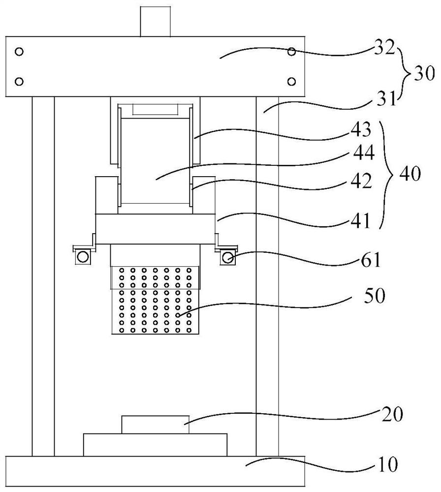
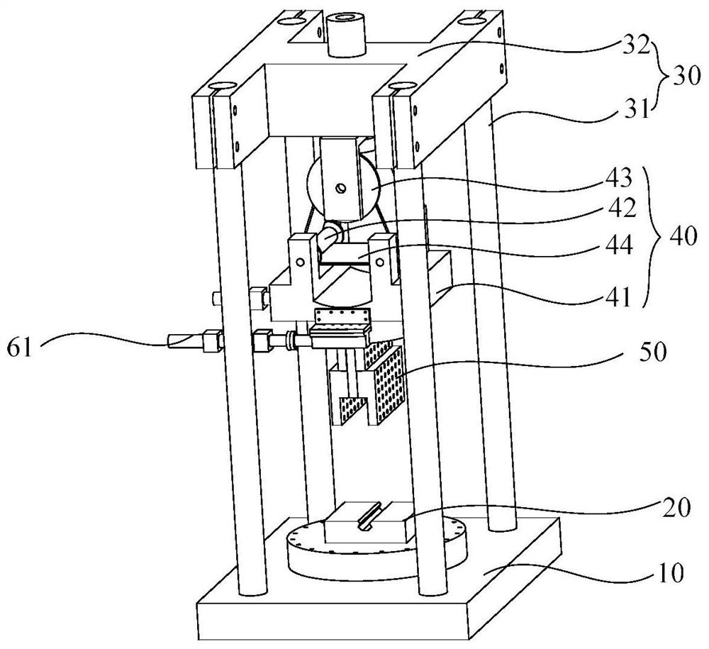
[0059] Such as Figure 5 and Figure 6 As shown, in one embodiment of the present application, the horizontal moving device 40 includes: a fixing part 45 and a sliding part 46 .

[0060] The fixing part 45 is connected with the rotating device, and a slide groove is arranged on the fixing part 45 .

[0061] The sliding part 46 is connected with the load applying device 60 , the sliding part 46 is provided with a slide rail, the sliding part 46 is connected with the fixed part 45 , and the slide rail is located in the slide groove, and the slide rail can move in the slide groove.

[0062] The load applying device 60 applies an external force to the sliding part 46, and through the cooperation of the chute and the slide rail, the sliding part 46 slides on the fixed part 45, so that the sliding seat 41 moves relative to the fixed pulley 43 and exerts an external force on the impeller in the horizontal direction .

[0063] In one embodiment of the present application, a plurali...


PUM


Abstract

The invention provides a low-cycle fatigue composite test device. The low-cycle fatigue composite test device comprises a base, a first chuck, a support, a lifting device, a rotating device, a horizontal moving device, a second chuck, a load applying device and a control device. The horizontal moving device is fixed to the rotating device and can move in the horizontal direction relative to the support. According to the load applying device, a horizontal pushing force or pulling force is applied to a blade through the horizontal moving device, the lifting device can apply a vertical pulling force and pressure to the blade, the rotating device can apply rotating forces in different directions to the blade, and an external force can be applied to the blade in multiple directions; and bending, twisting and multi-angle combined fatigue loading forms of the blade can be realized, and through the fatigue load and the strain distribution, the structural performance of the blade under the fatigue load can be evaluated. Therefore, the fatigue test can be fully performed on the blade.

Description

technical field [0001] The present application relates to the technical field of test devices, in particular, to a low-cycle fatigue composite test device. Background technique [0002] The blade is an important part of the fan. During the working process of the blade, the working environment of the blade is severe, and there are often low-cycle fatigue composite working conditions of the blade. At present, the existing blade fatigue tests mainly include the following methods: wind turbine blade double-hammer excitation loading vibration coupling characteristics and experimental research, design and research of two-axis fatigue loading system for wind turbine blades driven by hydraulic actuators, pendulum resonance type Research on fatigue loading system of wind turbine blades, fatigue test of wind turbine blades driven by eccentric mass, fatigue test of wind turbine blades driven by electric cylinder and design of excitation device for fatigue test of wind turbine blades dr...

Claims


Application Information

Patent Timeline
Patent Type & Authority Applications(China)
IPC IPC(8): G01M13/00
CPCG01M13/00Y02E10/72
Inventor 孙新杨果立成张莉李志兴李忠刚
Owner HARBIN INST OF TECH
Why Eureka
Try Eureka