


Quick Research
Generate reliable direction feasibility study reports for your R&D in just a few steps.

Technical Q&A
Discover and master advanced knowledge NOW. Basics, ideas, possibilities, all at once.

Find Solutions
As an expert in R&D theories, this can generate solutions to your technical problems instantly.

Evaluate Feasibility
Analyze your overall solution with one click, know your potential R&D risks in advance.

Monitor Landscape
Get weekly tech updates, stay abreast of the latest tech innovations and key insights.
Energy-saving concrete pouring and curing device and method
A kind of concrete and energy-saving technology, which is applied in the direction of construction, building structure, and building material processing. It can solve the problems of unstable concrete area, increased labor intensity of staff, and unstable concrete sprinkling range, so as to reduce labor. Intensity, Disturbance Reduction, Damage Reduction Effects
- Summary
- Abstract
- Description
- Claims
- Application Information
AI Technical Summary
Problems solved by technology
Method used
Image


Examples
Embodiment 1
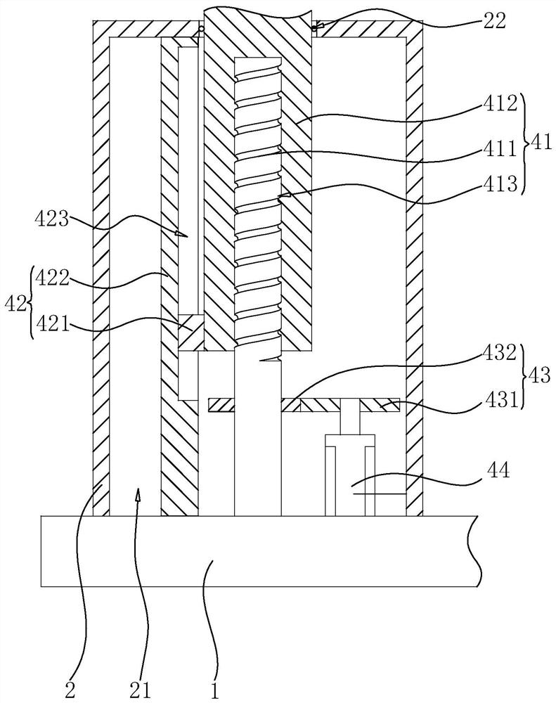
[0044] The embodiment of the application discloses an energy-saving concrete pouring and maintenance device. refer to figure 1 An energy-saving concrete pouring and maintenance device includes a base 1, a sprinkler 3, a lifting mechanism and a rotating mechanism. The base 1 is connected with the lifting mechanism, the lifting mechanism is connected with the rotating mechanism, and the rotating mechanism is connected with the spray head 3 . The lifting mechanism is used to adjust the height position of the nozzle 3 in the vertical direction, and the rotating mechanism is used to adjust the position of the nozzle 3 in the circumferential direction. The lifting mechanism and the rotating mechanism are used to adjust the position of the nozzle 3, thereby adjusting the spraying range of the nozzle 3 and improving applicability.
[0045] refer to figure 1 The base 1 is set in a plate shape, the base 1 is set on the ground along the horizontal direction, and the side of the base 1...
Embodiment 2
[0058] The embodiment of the present application discloses a method for an energy-saving concrete pouring and maintenance device, which includes the following steps:
[0059] S1, fill the water tank 13 with water that needs to be sprayed and maintained, and push the base 1 to the site that needs to be sprayed and maintained;
[0060] S2, start the lifting motor 44, the output shaft of the lifting motor 44 rotates and drives the first driving wheel 431 to rotate;
[0061] S3, the first driving wheel 431 is meshed with the first driven wheel 432 for transmission, the first driving wheel 431 drives the first driven wheel 432 to rotate, and the first driven wheel 432 drives the screw rod 411 to rotate;
[0062] S4, using the threaded hole 413, the screw mandrel 411 rotates, and the relative rotation between the screw mandrel 411 and the lifting shaft 412, the lifting shaft 412 slides back and forth along the length direction of the screw mandrel 411, thereby adjusting the height p...
PUM
 Abstract
Description
Claims
Application Information
 - R&D Engineer
- R&D Manager
- IP Professional
- Industry Leading Data Capabilities
- Powerful AI technology
- Patent DNA Extraction
Browse by: Latest US Patents, China's latest patents, Technical Efficacy Thesaurus, Application Domain, Technology Topic, Popular Technical Reports.
© 2024 PatSnap. All rights reserved.Legal|Privacy policy|Modern Slavery Act Transparency Statement|Sitemap|About US| Contact US: help@patsnap.com