
A workbench for hardware spray painting with clamping function

A workbench and hardware technology, applied in the direction of spraying devices, etc., can solve the problems of heavy weight, complex surface shape, overhead fixing, etc., and achieve the effect of reducing workload, shortening operation time, and wide processing range

Active Publication Date: 2022-07-19
肇庆市广兴美金属制品有限公司
View PDF15 Cites 0 Cited by
  • Summary
  • Abstract
  • Description
  • Claims
  • Application Information

AI Technical Summary

Problems solved by technology

[0003] When painting the hollow metal electrical casings and handicrafts, because the electrical casings and handicrafts are large in size, heavy in weight, and have complex surface shapes, ordinary painting workbenches cannot safely fix them overhead. If it is directly placed and painted directly on the work surface, the complex structure at the bottom cannot be painted, and it is necessary to wait for the painted surface to dry before turning over and painting, which will double the workload and operation time

Method used


Image

  • A workbench for hardware spray painting with clamping function
  • A workbench for hardware spray painting with clamping function
  • A workbench for hardware spray painting with clamping function

Examples


Embodiment 1

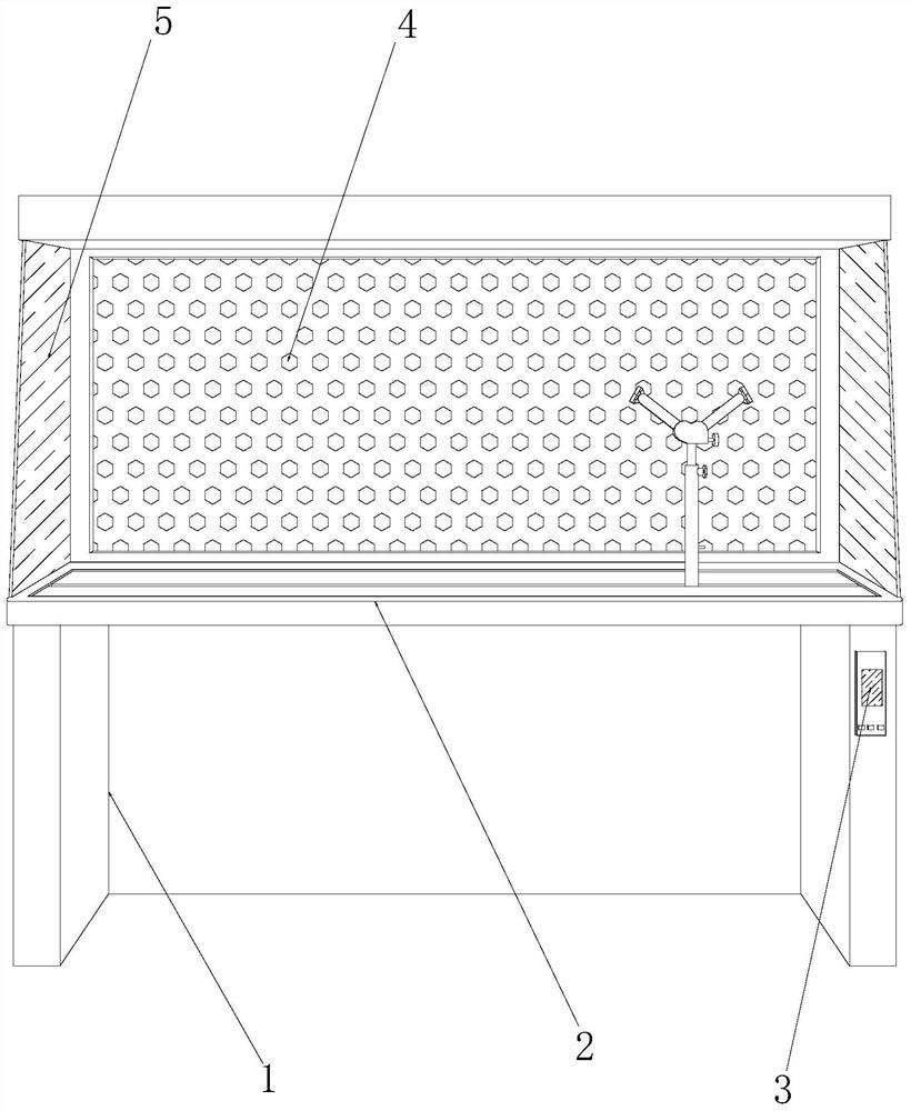
[0029] Example 1: Please refer to Figure 1-Figure 5 , the specific embodiment of the present invention is as follows:

[0030] The present invention provides a workbench for hardware spray painting with a clamping function. , the controller 3 is installed on the right end of the front of the bracket 1, the suction device 4 is embedded and connected to the upper rear end of the placing table 2, the partition plate 5 is provided with two pieces, and the two pieces of the partition plate 5 pass through respectively. The glue solution is bonded on the left and right sides above the placing table 2 .

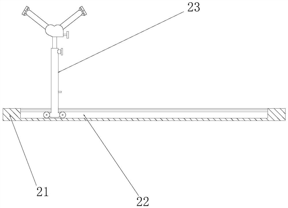
[0031] The placing table 2 is composed of a plate body 21, a slide rail 22, and a clamp 23. The plate body 21 is provided with a slide rail 22, and the slide rail 22 and the plate body 21 are integrated structures. Rail 22 is active in coordination.

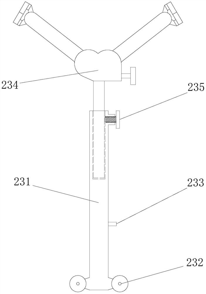
[0032] The fixture 23 is composed of a support frame 231, a roller 232, a limiting device 233, a fixer 234, and a locking bolt 235...

Embodiment 2

[0037] Example 2: Please refer to Figure 6-Figure 9 , the specific embodiment of the present invention is as follows:

[0038] The present invention provides a workbench for hardware spray painting with a clamping function. The fixer 234 is composed of a support rod 341, an angle adjuster 342, and an index rod 343. The upper part of the support rod 341 is welded and connected to the angle adjuster 342. Below, there are two indexing rods 343 , and the lower ends of the two indexing rods 343 are symmetrically installed inside the angle adjuster 342 respectively.

[0039] The angle adjuster 342 is composed of a casing 421, a worm 422, a knob 423, a first gear 424, a second gear 425, and a movable groove 426. The lower end of the inner wall of the casing 421 is movably engaged with a worm 422, and the left end of the knob 423 is welded. Connected to the right end of the worm 422, the outer ring of the first gear 424 is meshed above the worm 422, the second gear 425 is meshed wit...


PUM


Abstract

The invention discloses a workbench for hardware spray painting with clamping function. , the suction device is embedded and fixed on the rear end above the placing table, and the partitions are respectively bonded on the top of the placing table through the glue solution; Stable adjustment of the height and the left and right positions of the painting parts on the placing table enables the painting parts to be painted more conveniently and comprehensively. It adapts to the inner wall of various hollow metal electrical enclosures or handicrafts, and supports it in mid-air by magnetic force, so that the processing range of the equipment is wider, and the painted parts with complex structures can also be fully painted.

Description

technical field [0001] The invention relates to the field of painting processing in hardware production, and more particularly, to a workbench for painting hardware with clamping function. Background technique [0002] Hardware processing refers to the processing of raw materials such as stainless steel, copper, aluminum, iron, etc. through lathes, milling machines, drilling machines, polishing and other machinery according to drawings or samples to become various hardware parts. Large pieces of hardware products are all processed by spray painting, and the metal parts are prevented from rusting by spray painting. Generally, there are daily necessities, electrical shells, handicrafts, etc., but the existing technology has the following shortcomings: [0003] When painting the hollow metal electrical enclosures and handicrafts, because the electrical enclosures and handicrafts are large in size, heavy in weight, and complex in surface shape, the general painting workbench can...

Claims


Application Information

Patent Timeline
Patent Type & Authority Patents(China)
IPC IPC(8): B05B13/02
CPCB05B13/0271B05B13/0285
Inventor 施世棋
Owner 肇庆市广兴美金属制品有限公司
Learn More