Sensor support for arranging on a prosthesis

A technology of sensors and prostheses, applied in prosthesis, medical science, artificial arms, etc., can solve problems such as difficult to realize, time-consuming adaptation and familiar prosthesis, expensive prosthetic system, etc.

Pending Publication Date: 2021-07-23
SAPHENUS MEDICAL TECHNOLGY GMBH
View PDF2 Cites 0 Cited by
  • Summary
  • Abstract
  • Description
  • Claims
  • Application Information

AI Technical Summary

Problems solved by technology

[0003] The disadvantage of this known solution is that, on the one hand, such prosthetic systems are very expensive and, on the other hand, the phase of adaptation and familiarization with the prosthesis is very time-consuming for the prosthesis user
Additionally, these require multiple appointments with specialists and / or orthopedic surgeons
Stimulators and pressure transducers must be repositioned several times at the clinician, which may be difficult when they are already permanently installed

Method used


Image

  • Sensor support for arranging on a prosthesis
  • Sensor support for arranging on a prosthesis
  • Sensor support for arranging on a prosthesis

Examples


Embodiment Construction

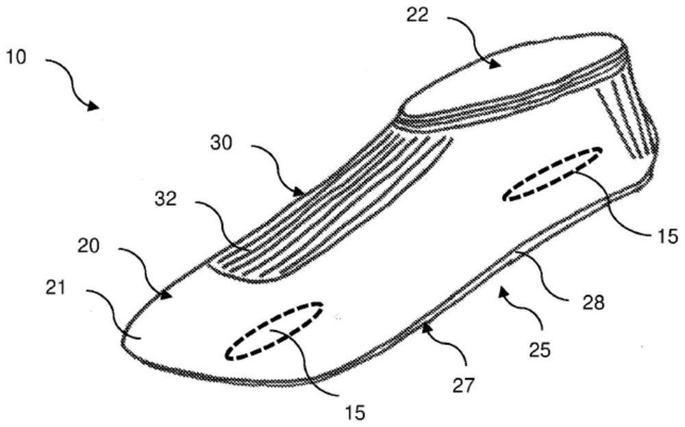
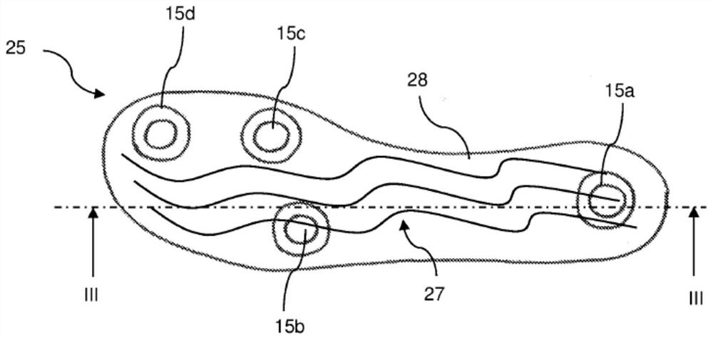
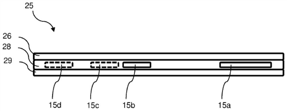
[0060] figure 1 A sensor carrier 10 is shown for arrangement on a prosthesis or a prosthesis part, wherein this prosthesis is, for example, an artificial foot. The sensor carrier 10 comprises a base body 20 consisting of a knitted fabric tube 21 which is closed at the (front) hose end and which has a fabric tube opening 22 at the (rear) hose end opposite the closed hose end . The base body 20 has a sensor section 25 with the sensor 15 (which is only shown symbolically) and a holding section 30 with a first knit structure 32 which enables the base body 20 to be fixedly held on the prosthetic component. The sensor section 25 has a different knit structure 27 than the first knit structure 32 , which enables a secure positioning of the sensor 15 relative to the prosthetic component. Arranged in the sensor section 25 is a sensor layer 28 in which the sensors 15 are arranged structured or systematically. Knitted structure 27 consists of durable synthetic fibers with a yarn thick...


PUM


Abstract

The invention relates to a sensor support (10) for arranging on a prosthesis, comprising a main part (20) for receiving sensors, said main part (20) having a sensor section (25) comprising sensors. The main part (20) has a holding section (30) for holding the main part (20) on a prosthesis part and a knitted fabric tube (21). The holding section (30) has a first knitted structure (32) which allows a secure hold of the main part (20) on the prosthesis part, and the sensor section (25) has a different knitted structure (27) which allows a secure positioning of the sensors relative to the prosthesis part.

Description

technical field [0001] The invention relates to a sensor carrier for arrangement on a prosthesis according to the preamble of claim 1 . Background technique [0002] Modern restorations often have sensors. The sensors are usually arranged directly inside the restoration and fixedly mounted therein. For example, multiple pressure sensors are installed in the prosthetic base of the prosthetic foot. Restorations often also have multiple stimulators. These stimulators are electrically connected to a plurality of pressure sensors. These stimulators are thus controlled or activated by pressure sensors and act through the skin on the patient's remaining limb. In this way, these stimulators allow the restoration user to "feel" the pressure on the bottom of the restoration by sensing the pressure on the pressure sensor. Such a device is disclosed, for example, in WO 98 / 25552 A1. [0003] The disadvantage of this known solution is that, on the one hand, such prosthetic systems a...

Claims


Application Information

Patent Timeline
IPC IPC(8): A61F2/50A61F2/54A61F2/60A61F2/66A61F2/76
CPCA61F2/54A61F2/60A61F2/66A61F2002/5001A61F2002/7615A61F2/583A61F2/70A61F2/76A61F2002/7635
Inventor 雷纳·舒尔蒂斯伯恩哈德·郎马丁·布兰德斯塔特亚伦·皮茨安德烈亚斯·穆伦伯连德
Owner SAPHENUS MEDICAL TECHNOLGY GMBH
Why Eureka
Try Eureka