
Energy storage and new energy power station reactive voltage coordinated control method and system

A technology of coordinated control and energy storage power station, applied in the field of power system, can solve problems such as coordination control limited to compensation analysis of energy voltage regulation characteristics, and achieve the effect of being beneficial to reactive power optimization, improving voltage control ability, and smoothing fluctuations

Active Publication Date: 2021-07-23
STATE GRID HENAN ELECTRIC POWER ELECTRIC POWER SCI RES INST +1
View PDF6 Cites 3 Cited by
  • Summary
  • Abstract
  • Description
  • Claims
  • Application Information

AI Technical Summary

Problems solved by technology

[0006] To sum up, under the current land-saving AVC control strategy, the coordinated control of optimal energy storage and reactive power voltage of new energy power stations is limited to the compensation analysis of energy voltage regulation characteristics

Method used


Image

  • Energy storage and new energy power station reactive voltage coordinated control method and system
  • Energy storage and new energy power station reactive voltage coordinated control method and system
  • Energy storage and new energy power station reactive voltage coordinated control method and system

Examples


Embodiment Construction

[0043] The principles and features of the present invention are described below in conjunction with the accompanying drawings, and the examples given are only used to explain the present invention, and are not intended to limit the scope of the present invention. In the following paragraphs the invention is described more specifically by way of example with reference to the accompanying drawings. Advantages and features of the present invention will be apparent from the following description and claims. It should be noted that all the drawings are in a very simplified form and use imprecise scales, and are only used to facilitate and clearly assist the purpose of illustrating the embodiments of the present invention.

[0044] Unless otherwise defined, all technical and scientific terms used herein have the same meaning as commonly understood by one of ordinary skill in the technical field of the invention. The terms used herein in the description of the present invention are ...


PUM


Abstract

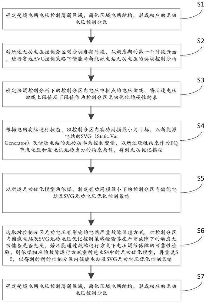
The invention relates to the technical field of power systems, in particular to an energy storage and new energy power station reactive voltage coordinated control method and system. The structure of a receiving end regional power grid is simplified, reactive voltage control partitions are formed, a control strategy is implemented in each time period, and then a reactive power optimization model in a normal operation mode is determined. According to the energy storage and SVG coordinated voltage control scheme, checking is conducted through the fault operation mode, if the checking is not passed, the reactive power optimization model under the fault operation mode is supervised, if the checking is passed, the energy storage power station and SVG coordinated voltage control scheme is determined, and analysis of the reactive power voltage optimization control strategy of the energy storage power stations and the SVG in the control partitions of all time periods of the dispatching period is completed repeatedly in the way. The method can effectively restrain the fluctuation of new energy output and the voltage fluctuation problem caused by the output fluctuation, and facilitates the reduction of the network loss of a control partitionand the guarantee of the power grid control effect of a central node. Therefore, the overall reactive power optimization of the power grid is facilitated, and the voltage control capability of the weak partitionof the receiving end power grid is improved.

Description

technical field [0001] The invention relates to the technical field of electric power systems, in particular to a coordinated control method and system for reactive power voltage of energy storage and new energy power stations. Background technique [0002] The proportion of new energy in the power grid is increasing, and the reasonable arrangement of its operation mode must fully consider its own ability to withstand the disturbance of new energy output fluctuations, so as to ensure the safe operation of the power grid and the reliable consumption of new energy. Most of the new energy stations are located at the end of the power grid, and the construction of the power grid is relatively weak. For the AC and DC receiving end power grid, it is more vulnerable to the impact of new energy output peak-valley difference and high-power disturbance, and the voltage stability is prominent. The large-scale energy storage system provides a new guarantee method for voltage stability th...

Claims


Application Information

Patent Timeline
Patent Type & Authority Applications(China)
IPC IPC(8): H02J3/16
CPCH02J3/16H02J2203/20Y02E40/30
Inventor 单瑞卿张振安崔惟刘玮蔚饶宇飞李程昊田春笋高泽刘芳冰高昆方舟
Owner STATE GRID HENAN ELECTRIC POWER ELECTRIC POWER SCI RES INST
Learn More