Spherical projectile body casting device

A projectile and projectile technology, which is applied to weapon types, weapons without explosives, offensive equipment, etc., can solve problems such as large difficulties, large size and weight of spheres, and inability to place spheres, and achieve the effect of increasing the range.

Pending Publication Date: 2021-07-23
河南省汇隆精密设备制造股份有限公司
View PDF6 Cites 0 Cited by
  • Summary
  • Abstract
  • Description
  • Claims
  • Application Information

AI Technical Summary

Problems solved by technology

[0002] When the launching device launches the sphere, due to the large volume and weight of the sphere, it is difficult to manually load it from the bullet inlet, the efficiency is low, and it is easy to affect the efficiency of erection. In view of the above problems, many automatic loading launchers have appeared on the market. , but most of the time when the current launching device automatically loads the launching sphere, through automatic control, each time a launching sphere is automatically loaded, the gas tightness of the launching device cannot be well guaranteed, and at the same time, the sphere cannot be placed in a suitable place every time. Launch location, so that it has a great impact on the range of the launch device

Method used


Image

  • Spherical projectile body casting device
  • Spherical projectile body casting device
  • Spherical projectile body casting device

Examples


Embodiment 1

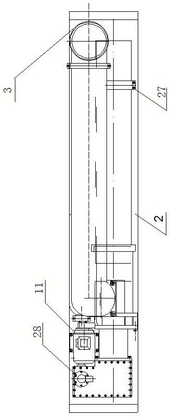
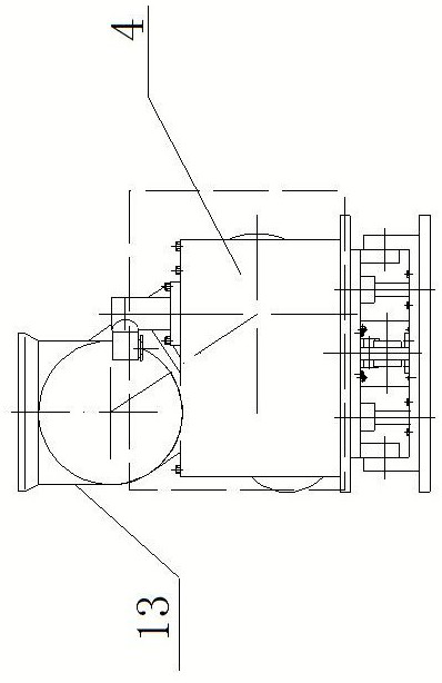
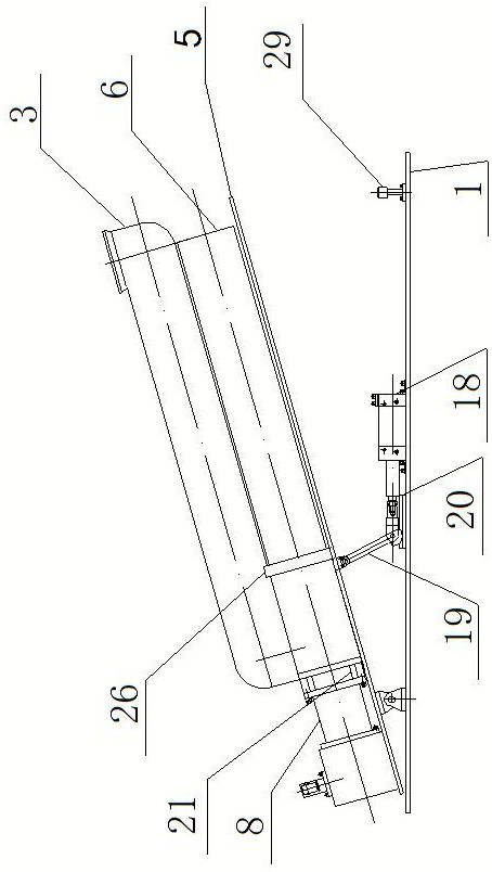
[0034] Embodiment 1: Reference figure 1 , figure 2 , image 3 , Figure 4 , Figure 5 , Figure 6 , Figure 7 and Figure 8 , a kind of ball projectile ejector of the present invention, comprises fixed plate 1, and a projectile that is arranged on fixed plate 1, and ejector includes the launching mechanism 2 that is arranged on fixed plate 1 top, projectile conveying cylinder 3, and The gas storage mechanism 4, the launch mechanism 2 includes the base plate 5 whose rear end is hinged with the fixed plate 1, the launch tube 6 fixedly installed on the base plate 5 through the launch pressure plate seat and the launch tube pressure plate 27, and the launch tube 6 through the fastening ring 26 and the launch tube 6. The connected launching seat 7, the connecting pipe 8 connected to the rear end of the launching seat 7 through the spacer sleeve 21, the rotatable bullet sleeve 9 arranged in the launching seat 7, the front and rear sliding top in the connecting pipe 8 Bullet ...

Embodiment 2

[0041] Embodiment two: reference image 3 , Figure 4 , Figure 5 , Figure 6 , Figure 7 , Figure 8 , Figure 9 , Figure 10 and Figure 11 , the structure of this embodiment is basically the same as that of Embodiment 1, and the similarities will not be repeated. The difference is that two ejectors are arranged on the fixed plate, and the two ejectors are arranged on the fixed plate in an opposite form. , one of the projectiles has its launch tube facing forward, and the other projectile's launch tube is facing backward.

[0042] By arranging two ejectors on the fixed plate, a spherical projectile ejector can launch balls in two directions forward and backward at the same time, which can meet the launching requirements of different places.


PUM


Abstract

The invention relates to a launching device, in particular to a spherical projectile body casting device which comprises a fixing plate and at least one casting device body arranged on the fixing plate. The casting device body comprises a launching mechanism, a projectile body conveying cylinder and an air storage mechanism which are arranged above the fixing plate. The launching mechanism comprises a bottom plate with one end hinged to the fixing plate, a launching cylinder fixedly arranged above the bottom plate, a launching base fixedly connected with the rear end of the launching cylinder, a connecting pipe connected with the rear end of the launching base, a projectile distributing sleeve rotationally arranged in the launching base, a projectile ejecting rod arranged in the connecting pipe in a front-back sliding mode, and a driving mechanism for driving the projectile distributing sleeve to rotate. When the projectile distributing sleeve rotates to a certain position, a ball is placed in the launching base, then the projectile distributing sleeve continues to rotate, redundant balls are blocked in the projectile body conveying cylinder, meanwhile, the projectile ejecting rod is driven to move forwards, the ball is pushed to the launching position, and the launching range of the launching device is greatly improved.

Description

technical field [0001] The invention relates to a launching device, in particular to a spherical projectile ejector. Background technique [0002] When the launching device launches the sphere, due to the large volume and weight of the sphere, it is difficult to manually load it from the bullet inlet, the efficiency is low, and it is easy to affect the efficiency of erection. In view of the above problems, many automatic loading launchers have appeared on the market. , but most of the time when the current launching device automatically loads the launching sphere, through automatic control, each time a launching sphere is automatically loaded, the gas tightness of the launching device cannot be well guaranteed, and at the same time, the sphere cannot be placed in a suitable place every time. The location of the launch, so that it has a great impact on the range of the launch device. Contents of the invention [0003] Aiming at the problems in the prior art, the object of ...

Claims


Application Information

Patent Timeline
IPC IPC(8): F41B11/50F41B11/681
CPCF41B11/50F41B11/681
Inventor 马建连捷
Owner 河南省汇隆精密设备制造股份有限公司
Why Eureka
Try Eureka