
A device for dissipating impeller wake vortex in stall condition of mixed flow pump

A mixed-flow pump and dissipation technology, which is applied to components, pumps, and pump elements of pumping devices used for elastic fluids, and can solve the problem that there is no correlation between the improvement or elimination of the wake vortex of the mixed-flow pump impeller, and the vortex structure cannot be effectively improved. To achieve the effect of expanding the flow working range, improving efficiency and improving the flow field structure

Active Publication Date: 2022-05-27
JIANGSU UNIV
View PDF5 Cites 0 Cited by
  • Summary
  • Abstract
  • Description
  • Claims
  • Application Information

AI Technical Summary

Problems solved by technology

[0003] After retrieval, the patent with the application number CN201820156382.0 injects high-pressure water into the water injection hole inside the guide vane body, and then the high-pressure water jets into the guide vane blades to the flow channel along the jet hole on the guide vane suction surface, and enters the space between the guide vane blades. The jet breaks up the stall vortex, but this method is only suitable for pumps with thick guide vane blades, and it is to eliminate the stall vortex in the guide vane, and cannot effectively improve the vortex structure generated by the impeller wake
[0004] After searching, there are currently no relevant patent applications and documents for the improvement or elimination of the wake vortex of the impeller of the mixed-flow pump under the stall condition.

Method used


Image

  • A device for dissipating impeller wake vortex in stall condition of mixed flow pump
  • A device for dissipating impeller wake vortex in stall condition of mixed flow pump
  • A device for dissipating impeller wake vortex in stall condition of mixed flow pump

Examples


Embodiment Construction

[0025] In order to make the objectives, technical solutions and advantages of the present invention clearer, the present invention will be further described in detail below with reference to the accompanying drawings and embodiments. It should be understood that the specific embodiments described herein are only used to explain the present invention, but not to limit the present invention.

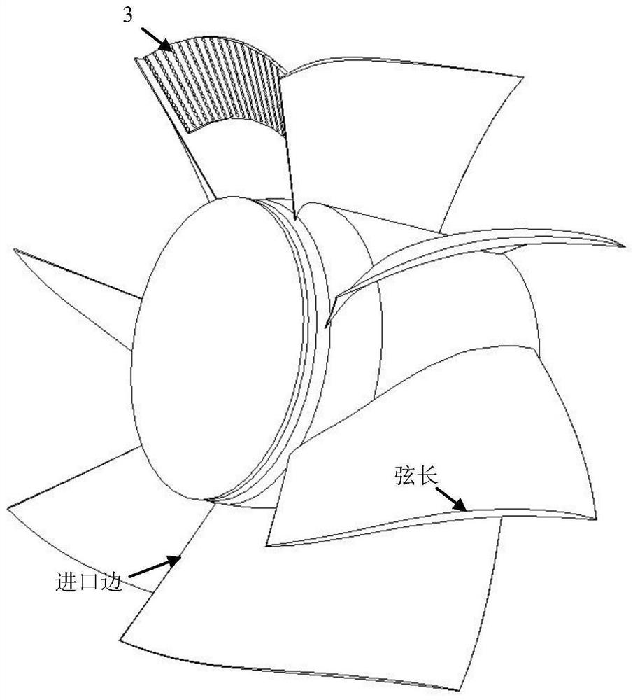
[0026] An impeller wake vortex dissipating device in a stall condition of a mixed-flow pump, comprising a guide vane 2 , a wake vortex dissipating device 3 and an outer casing 11 . There are N guide vanes 2 evenly distributed on the guide vane hub 1; the guide vanes 2 evenly divide the inside of the pump into N flow passages; a wake vortex dissipation device 3 is arranged in each flow passage divided by the guide vanes 2, such as Figure 5 shown. The wake vortex dissipating device 3 is fixedly installed inside the outer casing 11 , and the wake vortex dissipating device 3 is located in th...


PUM


Abstract

The invention discloses a wake vortex dissipating device for an impeller in a stall condition of a mixed-flow pump, which includes a guide vane and a wake vortex dissipating device; N uniformly distributed guide vanes divide the inside of the pump into N guide vane channels; A wake vortex dissipation device is installed in each guide vane flow channel, and one end of the wake vortex dissipation device is fixedly connected to the inner wall of the pump, so each wake vortex dissipation device is located in the middle and upper part of the guide vane flow channel, and does not occupy the guide vane below. The blade flow channel; the wake vortex dissipating device is provided with a pair of dissipation holes, and the energy of the wake vortex of the impeller is dissipated by using the pair of dissipation holes.

Description

technical field [0001] The invention belongs to the technical field of fluid machinery (pump) internal flow, in particular to an impeller wake vortex dissipation device in a stalled working condition of a mixed-flow pump. Background technique [0002] Mixed-flow pump is a pump type whose specific speed is between centrifugal pump and axial-flow pump. It has the characteristics of axial inflow and oblique outflow. With the wide application of mixed-flow pumps in the fields of sewage treatment, flood control and drainage, and farmland irrigation, the requirements for their performance are gradually increasing. However, because the design theory of the mixed-flow pump is not perfect, there is currently no ability to design a mixed-flow pump with the highest efficiency under full flow conditions. In general, when the flow conditions of the mixed-flow pump deviate from the design point, the pump efficiency will decrease. Especially as the flow rate decreases, the efficiency of ...

Claims


Application Information

Patent Timeline
Patent Type & Authority Patents(China)
IPC IPC(8): F04D29/18F04D29/66
CPCF04D29/18F04D29/669F04D31/00F04D29/181F04D29/448F04D11/00F04D29/44
Inventor 季磊磊李伟周岭朱勇马斯卓齐寒东
Owner JIANGSU UNIV
Learn More