
Combined reinforced joint for connection of steel beam and wide concrete filled steel tubular column

A technology for concrete filled steel tubular columns and concrete columns, which can be applied to buildings and building structures, etc., can solve problems such as easy protruding, affect the appearance of buildings, and cannot be poured with concrete, so as to improve the stress state, improve the seismic ductility, and ensure the rigidity and strength. Effect

Active Publication Date: 2021-07-23
凉山州现代房屋建筑集成制造有限公司 +2
View PDF23 Cites 0 Cited by
  • Summary
  • Abstract
  • Description
  • Claims
  • Application Information

AI Technical Summary

Problems solved by technology

Partially through diaphragms need to be inserted when the weak axis is connected, which will form a partially closed area and cannot be poured with concrete; the externally attached plate connection node is easy to protrude at the lower flange, which affects the appearance of the building and the installation of the window frame at the lower part of the beam

Method used


Image

  • Combined reinforced joint for connection of steel beam and wide concrete filled steel tubular column
  • Combined reinforced joint for connection of steel beam and wide concrete filled steel tubular column
  • Combined reinforced joint for connection of steel beam and wide concrete filled steel tubular column

Examples


Embodiment 1

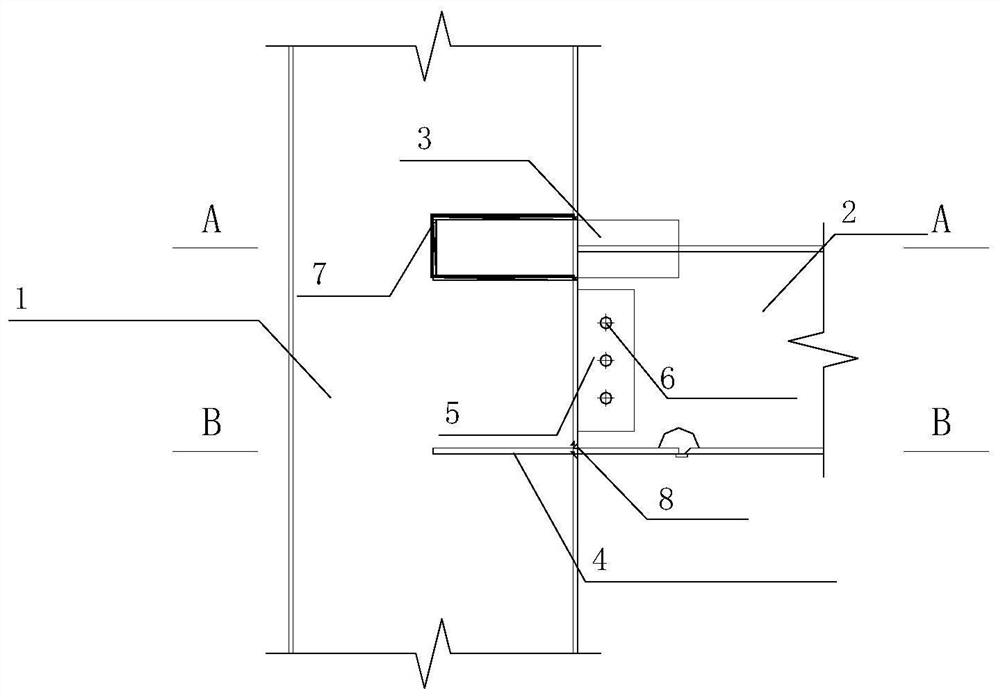
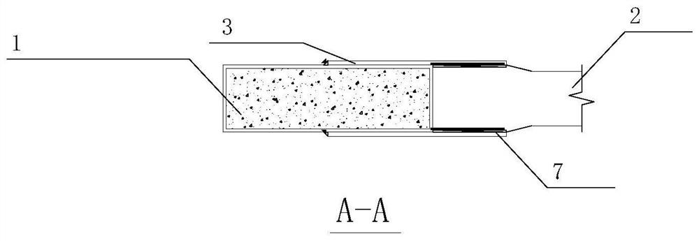
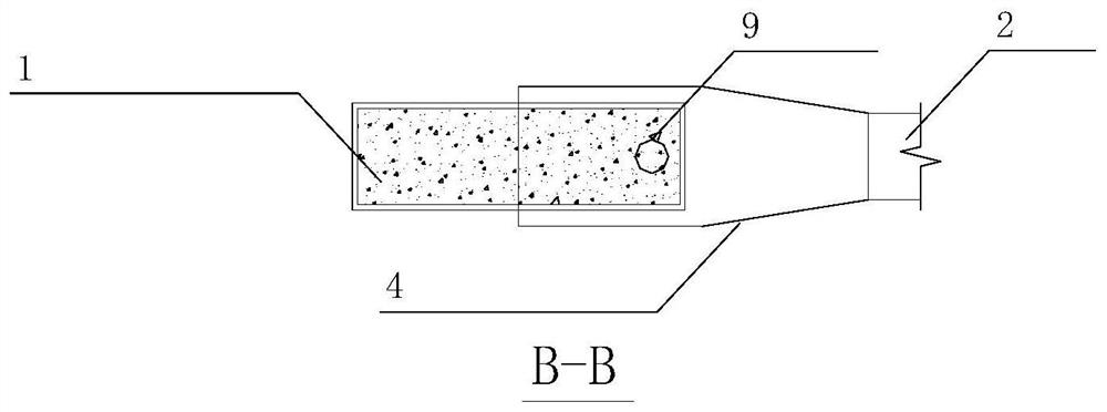
[0052] Such as Figure 1-3 Shown, the present invention comprises wide steel pipe concrete column 1, steel girder, outer sticking board, part through transverse diaphragm, connecting plate and vertical inserting plate; figure 1 As shown, the short side of the wide CFST column 1 is connected to the steel beam, and the upper flange, lower flange, and web of the steel beam are respectively connected to the wide The short sides of the steel tube concrete column 1 are connected to the column walls. The wide steel pipe concrete column 1 is formed by pouring concrete inside a rectangular steel pipe, and the ratio of the long side to the short side of the rectangular steel pipe is 1-4. The steel beam is an H-shaped steel beam, and the flange of the steel beam is welded to the column wall of the wide steel pipe concrete column 1.

[0053] One short side of the wide steel pipe concrete column 1 is connected to the first steel beam 2 after passing through two first external panels 3 , ...

Embodiment 2

[0057] Such as Figure 4-6 As shown, when the wide concrete-filled steel tube column 1 is located in the middle of the building plane, the two sides of the long side of the wide steel tube concrete column 1 are respectively connected to two steel beams through vertical inserts, and the vertical inserts are respectively connected to the external laminate and part of the The diaphragms are connected.

[0058] When the wide concrete-filled steel tube column 1 is located in the middle of the building plane, the other short side of the wide steel tube concrete column 1 passes through two second external panels 13, a second partly penetrating transverse partition 15, a second connecting plate and the fourth Steel beams 22 are connected;

[0059] One side of the upper flange of the fourth steel beam 22 and the side where the long side of the wide steel pipe concrete column 1 is located are connected by a second external plate 13, the other side of the upper flange of the fourth stee...


PUM


Abstract

The invention discloses a combined reinforced joint for connection of a steel beam and a wide concrete filled steel tubular column. The combined reinforced joint comprises a wide steel pipe concrete column, steel beams, outer flitch plates, a locally-through transverse partition plate, a connecting plate and vertical inserting plates; the short edge of the wide steel pipe concrete column is connected with the steel beams, and upper flanges, lower flanges and web plates of the steel beams are connected with the column wall of the short edge of the wide steel pipe concrete column after passing through the two outer flitch plates, the local-through transverse partition plate and the connecting plate; when the wide steel pipe concrete column is located in the middle of a building plane, the two sides of one end of the long edge of the wide steel pipe concrete column are connected with the two steel beams through the vertical inserting plates correspondingly, and the vertical inserting plates are connected with the outer flitch plates and the locally-through transverse partition plate correspondingly. The invention provides a construction method for simultaneously rigidly connecting the wide steel pipe concrete column with the steel beams in a strong axis direction and a weak axis direction. The rigidity and strength of the joint and the joint connecting area can be guaranteed, plastic hinges appear on the steel beams, the ductility coefficient of the joint reaches 5.5 or above, and the design target of strong joints and weak components can be achieved.

Description

technical field [0001] The invention relates to a combined reinforced joint used for connecting steel beams and wide concrete-filled steel tube columns, which can be widely used in the rigid connection between H-shaped steel beams and wide steel-filled concrete columns in multi-story steel structures. Background technique [0002] In the multi-story steel structure, the steel beams are mostly H-shaped steel beams, and the steel columns are mostly rectangular steel tube concrete columns. The rigid connection of steel beams and steel columns is the most basic measure to provide the overall rigidity and seismic performance of the structure. At present, the commonly used rigid joint is to set a transverse diaphragm at the position corresponding to the beam flange of the steel column, and the internal force of the steel beam flange is transmitted to the steel column through the diaphragm, thus forming a rigid joint. There are two types of diaphragms: inner diaphragm and through ...

Claims


Application Information

Patent Timeline
IPC IPC(8): E04B1/18E04B1/58
CPCE04B1/185E04B1/58
Inventor 袁尉卿付波庞仙台周有波潘涛张悦胡朝坤邱某
Owner 凉山州现代房屋建筑集成制造有限公司
Learn More