Process for laser welding of joints of of pipelines and plates

A laser welding and pipeline technology, applied in laser welding equipment, welding equipment, manufacturing tools, etc., can solve the problems of laser refraction, laser head pollution, laser head burnout, etc., and achieve the effect of avoiding falling

Pending Publication Date: 2021-07-23
山西奥斯腾科技有限责任公司
View PDF5 Cites 0 Cited by
  • Summary
  • Abstract
  • Description
  • Claims
  • Application Information

AI Technical Summary

Problems solved by technology

When the laser head turns to the bottom of the pipe and welds upward, welding spatter and residues will easily fall into the welding head, polluting the inside of the laser head, and then easily refracting the laser inside the laser head, causing the laser head to burn out

Method used


Image

  • Process for laser welding of joints of of pipelines and plates
  • Process for laser welding of joints of of pipelines and plates

Examples


Embodiment Construction

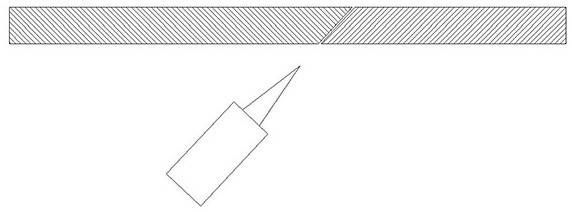
[0011] Such as figure 1 , figure 2 As shown, the present invention is a process for laser welding pipe and plate seams, the welding surface of the pipes and plates to be welded is processed into an inclined surface, and the welded joints can be matched and assembled together, and then the welding head is tilted. welding.

[0012] Process the lower end of the welded joint into a V-shaped groove. And this V-shaped groove is only needed when necessary, for example, when the weld seam is very thick, and the base metal is not thick and can be penetrated at one time, this groove can be omitted.

[0013] After the welding head is set obliquely, its axial direction coincides with the surface where the splicing seam is located.

[0014] In the present invention, the welding head is arranged under the welding seam, and the inclination direction of the welding head and the seam is consistent, so that welding impurities can fall naturally, and the inclined seam can better prevent weld...


PUM


Abstract

The invention provides a process for laser welding of of joints of pipelines and plates in order to overcome the defects in the prior art. Welding impurities and splashes are prevented from falling into a welding head to damage the welding head. In order to solve the technical problem, the technical scheme adopted by the invention is as follows: according to the process for laser welding of the joints of the pipelines and the plates, the welding surfaces of the pipelines and the plates which need to be welded are machined into inclined surfaces, the welded splicing positions can be spliced together in a matched manner, and then the welding head is inclined for welding; and when a welding material is too thick, the lower ends of the welded splicing positions are machined into V-shaped grooves, and after the welding head is obliquely arranged, the axial direction of the welding head coincides with the faces where the splicing joints are located.

Description

technical field [0001] The invention relates to a process for laser welding pipes and plate joints, which belongs to the technical field of laser welding. Background technique [0002] In the existing laser welding process, when the welding environment requires, the welding head must be below the weld seam and weld upward, such as field pipeline welding, the oil pipeline is fixed and cannot be rotated, and the laser head needs to rotate around the pipeline and weld. When the laser head turns to the bottom of the pipe and welds upward, welding spatter and residues will easily fall into the inside of the welding head, polluting the inside of the laser head, and then easily refracting the laser inside the laser head, causing the laser head to burn out. Contents of the invention [0003] The invention overcomes the deficiencies in the prior art, provides a process for laser welding pipes and plate joints, and prevents welding impurities and spatter from falling into the weldin...

Claims


Application Information

Patent Timeline
IPC IPC(8): B23K26/282B23K26/70
CPCB23K26/282B23K26/702
Inventor 杨军赵悦如杨林达
Owner 山西奥斯腾科技有限责任公司
Why Eureka
Try Eureka