
Automatic pitting device of metal pipe drawing equipment

A drawing equipment and metal tube technology, which is applied to metal drawing forming tools, metal processing equipment, metal wire drawing, etc., can solve the problems of core head displacement, high labor intensity, and reduced production efficiency, and avoid empty drawing. And the effect of broken pipes, reducing labor intensity and improving production efficiency

Pending Publication Date: 2021-07-20
SHANGHAI LONGYANG PRECISE COMPOUND COPPER TUBE CO LTD
View PDF2 Cites 0 Cited by
  • Summary
  • Abstract
  • Description
  • Claims
  • Application Information

AI Technical Summary

Problems solved by technology

The position and size of the pits are not uniform, often resulting in the phenomenon of empty pulling and breaking the tube, and the positioning is not allowed to hit the inner core of the metal tube, causing damage to the core. After the core is damaged, it is not easy to find, directly causing scratches on the inner wall of the metal tube. As a result, the yield of the metal pipe is low, which reduces the production efficiency and increases the production cost. On average, the operator needs to tap 3 to 6 times for each hole. The labor intensity is high and it is easy to cause industrial accidents.
There are also some methods that use the method of installing the pitting device on the trolley to realize automatic pitting. In this way, after the trolley pulls out a section of pipe, the core head may run due to the vibration of the trolley, and the pit is hit in front of the core head. At this time, it is necessary to cut off the tube head again and press the tip of the core again, which is time-consuming and labor-intensive.
[0004] At present, there is a Chinese patent authorization announcement number CN206567397U which discloses an automatic pitting device for metal pipe drawing equipment. Although the patent pits the metal pipe through a pitting mechanism, the pitting mechanism of the patent is fixed on the drawing On the trolley, the core head may move due to the pulling stop and vibration of the drawing trolley, and the hole-making mechanism cannot effectively control the distance and depth of the hole, and the above-mentioned problems still exist

Method used


Image

  • Automatic pitting device of metal pipe drawing equipment
  • Automatic pitting device of metal pipe drawing equipment
  • Automatic pitting device of metal pipe drawing equipment

Examples


Embodiment Construction

[0020] In order to make the technical means, creative features, objectives and effects achieved by the present invention easy to understand, the present invention will be further elaborated below.

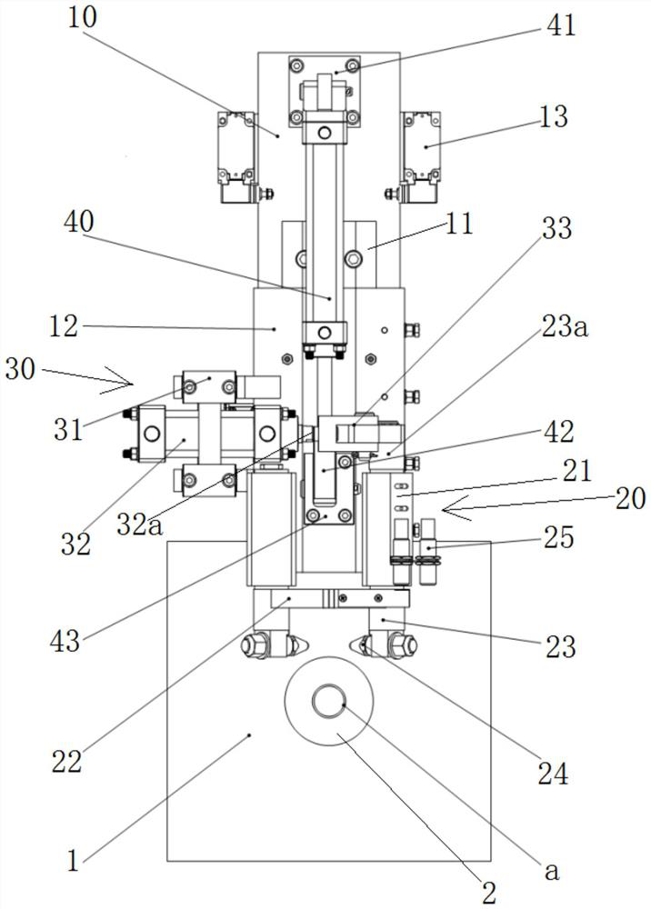
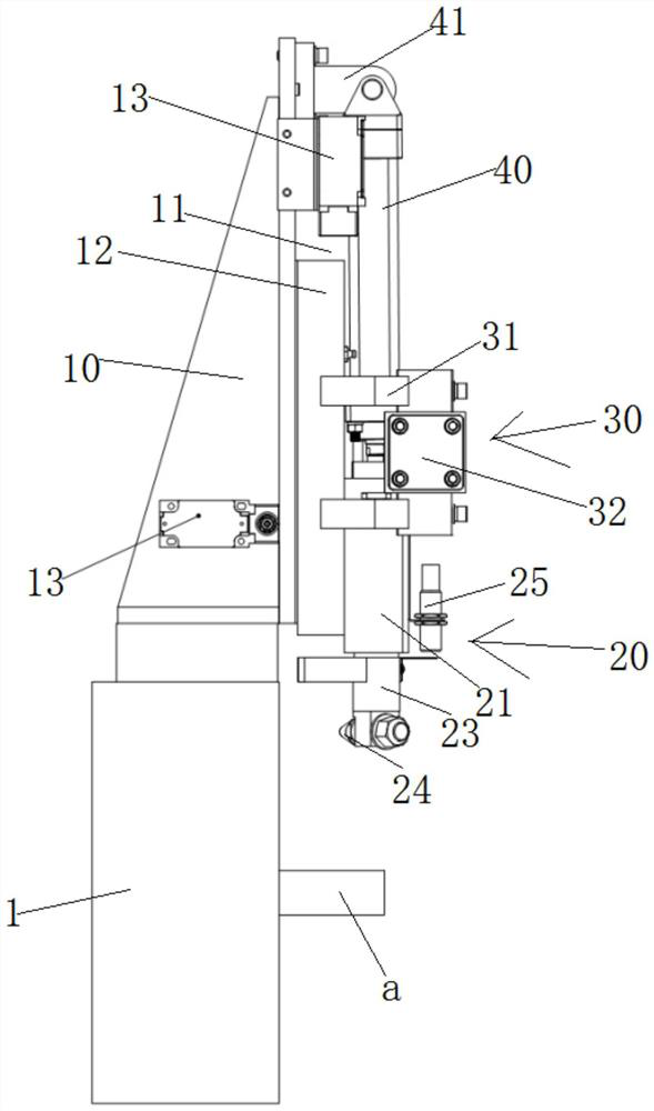
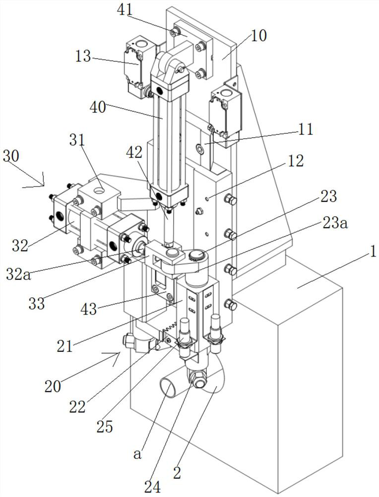
[0021] see Figure 1 to Figure 3 The shown automatic pitting device of a metal drawing equipment includes a mounting frame 10 arranged on the mold wall 1 and a pitting device 20 which is slidably arranged on the mounting frame 10 and is used to pit the metal pipe a and A hydraulic drive device 30 is slidably arranged on the installation frame 10 and used to drive the drilling device 30 to work. The mold wall 1 in this embodiment is provided with a through hole 2 matching with the metal pipe a. It is convenient to pull out the trolley to pass the metal pipe a through the through hole 2.

[0022] The hydraulic drive unit 30 is connected with the pit device 20, and the mounting frame 10 is also provided with a lifting device 40 for driving the pit device 20 to move up and down, and ...


PUM


Abstract

The invention discloses an automatic pitting device of metal pipe drawing equipment. The automatic pitting device of the metal pipe drawing equipment comprises a mounting frame arranged on a mold wall, a pitting device arranged on the mounting frame in a sliding manner and used for pitting a metal pipe and a hydraulic driving device arranged on the mounting frame in a sliding manner and used for driving the pitting device to work; the hydraulic driving device is connected with the pitting device; a lifting device used for driving the pitting device to move up and down is further arranged on the mounting frame; and the pitting device, the hydraulic driving device and the lifting device are connected with a control system. Compared with a manual pitting mode in the prior art, the automatic pitting device of the metal pipe drawing equipment has the advantages that the pitting distance and depth are effectively controlled, empty drawing and pipe breaking are avoided, the labor intensity of workers is reduced, the yield is increased, and the production efficiency is improved.

Description

technical field [0001] The invention relates to the technical field of metal pipe drawing processing equipment, in particular to an automatic pitting device for metal pipe drawing equipment. Background technique [0002] Double drawing is an important process in the production of metal casting and rolling. The drawing process adopts the drawing of the floating core. After the core is loaded into the rolled tube, it needs to be pitted and positioned before drawing to prevent the core from running. , resulting in empty pull. [0003] In the second pass of the current metal pipe, it is necessary to manually punch a small pit on the surface of the metal pipe to clamp the core to prevent the core from running. The size and position of the pit produced by this manual pitting method Uncertain, mainly based on the operator's work experience to decide. The position and size of the pits are not uniform, often resulting in the phenomenon of empty pulling and breaking the tube, and th...

Claims


Application Information

Patent Timeline
Patent Type & Authority Applications(China)
IPC IPC(8): B21C1/22B21C3/00B21C37/06B21D22/14B21D28/28
CPCB21C1/22B21C3/00B21C37/06B21D22/14B21D28/28
Inventor 李文科葛留帅武国朋刘奇
Owner SHANGHAI LONGYANG PRECISE COMPOUND COPPER TUBE CO LTD
Learn More