
Leakage-proof testing device for heating and ventilation pipeline

A test device and pipeline technology, which is applied in the direction of liquid tightness measurement using liquid/vacuum, can solve problems such as underpressure, pipeline overpressure, unsatisfactory test results, etc., achieve uniform mixing, avoid manual closing, The effect of improving the service life of equipment

Pending Publication Date: 2021-07-16
陈亮
View PDF12 Cites 2 Cited by
  • Summary
  • Abstract
  • Description
  • Claims
  • Application Information

AI Technical Summary

Problems solved by technology

[0004] In the existing leak-proof test device, when the pressure is close to the test pressure during the pressurization process, the device needs to be closed manually, so that the device is not closed in time, which is likely to cause overpressure or underpressure in the pipeline, making the test results unsatisfactory. Therefore, a solution is proposed

Method used


Image

  • Leakage-proof testing device for heating and ventilation pipeline
  • Leakage-proof testing device for heating and ventilation pipeline
  • Leakage-proof testing device for heating and ventilation pipeline

Examples


Embodiment 1

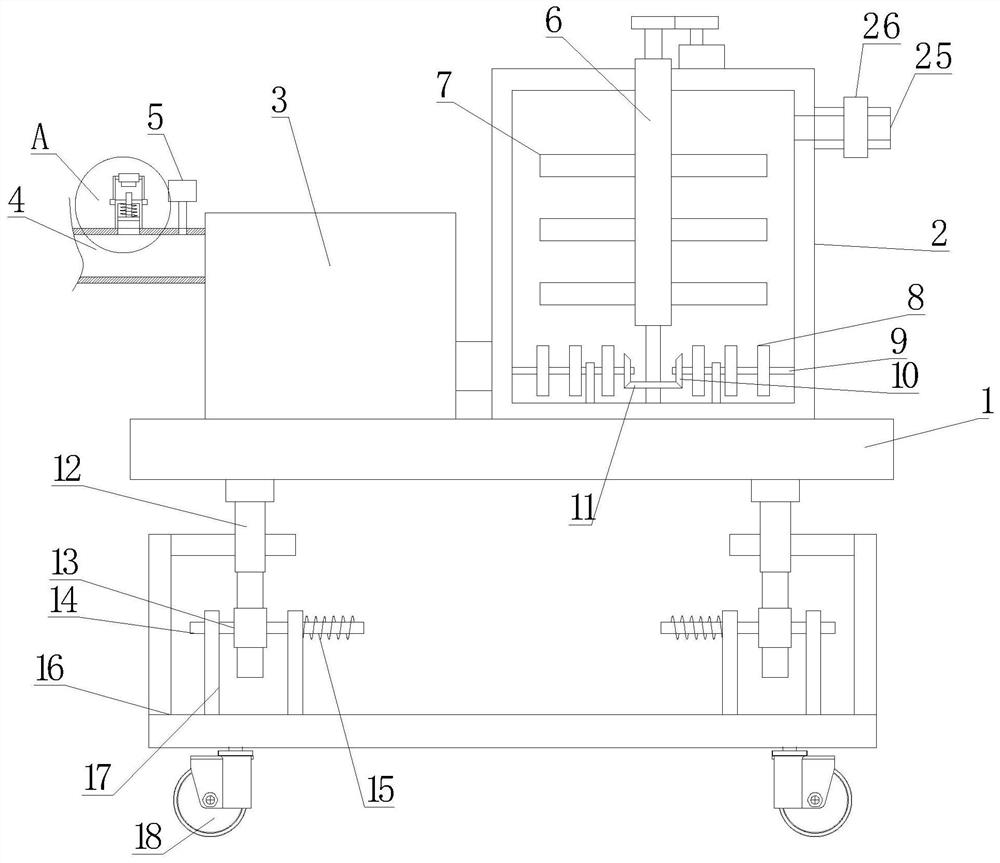
[0024] see Figure 1~3 , in Embodiment 1 of the present invention, it is a structural diagram of a leak-proof testing device for heating and ventilation pipes provided by the embodiment of the present invention, including: a mounting base 1, and a pressure pump 3 and a liquid storage device are arranged on the mounting base 1 In the tank 2, the pressure pump 3 is provided with a first stirring part and a second stirring part inside, and the stirring directions of the first stirring part and the second stirring part are different;

[0025] The input end of the pressure pump 3 communicates with the interior of the liquid storage tank 2 through a pipeline, and the liquid storage tank 2 is used to store water containing cleaning fluid, so that the pipeline can be cleaned during the test process.

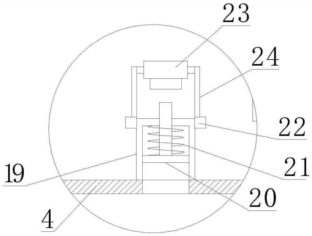
[0026] The pressure supply pump 3 is provided with an output pipe 4, and the output pipe 4 is provided with a voltage stabilizing member 19. The inside of the voltage stabilizing member ...

Embodiment 2

[0031] see Figure 1~3 , The main difference between Embodiment 2 and Embodiment 1 is that the height of the position switch 23 is adjustable, so that it is convenient to meet the requirements of different test pressures.

[0032] Specifically, the outer side of the position switch 23 is connected with a connecting piece 24, and the connecting piece 24 is connected to the adjusting sleeve 22, and the height of the adjusting sleeve 22 is installed on the voltage stabilizing piece 19, so that when the height needs to be adjusted , adjust the position of the adjusting sleeve 22 on the pressure stabilizing member 19 to adjust the height of the position switch 23 , and then realize the closing of the pressure pump 3 at different pressures.

[0033] The adjusting sleeve 22 is mounted on the outside of the voltage stabilizing member 19 through threads, and the connecting member 24 is rotatably mounted on the adjusting sleeve 22 , so that the position switch 23 is prevented from rotat...


PUM


Abstract

The invention is suitable for the technical field of engineering equipment, and provides a leakage-proof testing device for a heating and ventilation pipeline. The device comprises a mounting base, wherein a pressure supply pump and a liquid storage tank are arranged on the mounting base, a first stirring part and a second stirring part are arranged in the pressure supply pump, and the stirring directions of the first stirring part and the second stirring part are different; the input end of the pressure supply pump communicates with the interior of the liquid storage tank through a pipeline, the liquid storage tank is used for storing water containing cleaning liquid, an output pipe is arranged on the pressure supply pump, a pressure stabilizing part is arranged on the output pipe, the interior of the pressure stabilizing part is hollow, the interior of the pressure stabilizing part communicates with the interior of the output pipe, and a sliding block is arranged in the pressure stabilizing part in an up-down sliding mode; the upper end of the sliding block penetrates through the upper end of the pressure stabilizing part, the sliding block is sleeved with a first elastic part, the two ends of the first elastic part are fixedly installed on the sliding block and the pressure stabilizing part respectively, and a position switch is further arranged on the pressure stabilizing part and used for controlling the pressure supply pump to stop working; the mounting base is mounted on the base through a damping mechanism.

Description

technical field [0001] The invention relates to the technical field of engineering equipment, in particular to a leak-proof testing device for heating and ventilation pipelines. Background technique [0002] The thickness and specifications of the HVAC pipes can be changed according to the requirements. Usually, when connecting, the two ends of the air pipes are always externally connected to the fittings (such as elbows, reducing diameters). Under normal circumstances, there are no grooves at both ends of the heating and ventilation pipes and there are sealing rings. [0003] Nowadays, the heating pipes in many buildings are laid underground. It is often necessary to test the tightness of the heating and ventilation pipes before decoration to test whether there are leaks in the heating and ventilation pipes to ensure normal heating in the later period. [0004] In the existing leak-proof test device, when the pressure is close to the test pressure during the pressurization...

Claims


Application Information

Patent Timeline
Patent Type & Authority Applications(China)
IPC IPC(8): G01M3/02
CPCG01M3/02
Inventor 陈亮
Owner 陈亮
Learn More