
A water level measuring device for reservoir engineering management

A technology for engineering management and water level measurement, which is applied in the direction of buoy liquid level indicators, etc., can solve the problems that the water level data is not enough to accurately reflect the real water level of the reservoir, the error of the water level detection result increases, and the detection error increases, achieving high accuracy , reduce the measurement error, improve the effect of practicality

Active Publication Date: 2022-08-02
承德水创工程项目咨询有限公司
View PDF6 Cites 0 Cited by
  • Summary
  • Abstract
  • Description
  • Claims
  • Application Information

AI Technical Summary

Problems solved by technology

[0003] The existing water level measuring device for reservoir engineering management is mainly composed of machine base, float, balancer, chain, water level wheel, photoelectric code sensor, etc. When in use, the water level rises first, then the float floats up, and then the balancer sinks and pulls the chain , then the chain rotates with the water level wheel, and then the photoelectric encoder sensor senses the rotation of the water level wheel and converts it into a value, which is used to measure the change of the water level. However, a part of the float is exposed above the water surface, which will make the float It is easy to pull the chain under the action of wind, and then make the water level wheel rotate, resulting in an increase in the error of the water level detection result. Zipper chain, which will also cause the chain to move, which will cause the water level wheel to rotate, which will further increase the detection error, resulting in the measured water level data not being enough to accurately reflect the real water level of the reservoir. Therefore, it is urgent to design a water level for reservoir engineering management. measuring device

Method used


Image

  • A water level measuring device for reservoir engineering management
  • A water level measuring device for reservoir engineering management
  • A water level measuring device for reservoir engineering management

Examples


Embodiment Construction

[0035] The technical solutions in the embodiments of the present invention will be clearly and completely described below with reference to the drawings in the embodiments of the present invention; obviously, the described embodiments are only a part of the embodiments of the present invention; rather than all the embodiments. Based on the embodiments of the present invention; all other embodiments obtained by those of ordinary skill in the art without creative work; all belong to the protection scope of the present invention.

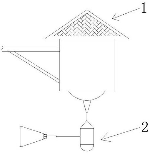
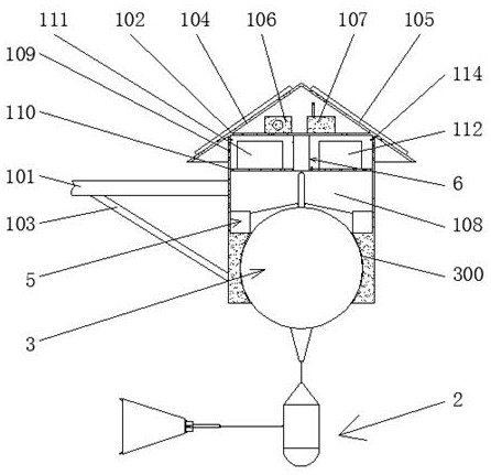
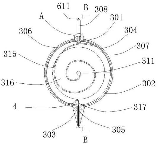
[0036] see Figure 1-13 , a water level measurement device for reservoir engineering management, comprising a measurement main body 1, and a floating device 2 is arranged at the bottom of the measurement main body 1.

[0037] The measurement main body 1 includes a support rod 101 , the right end of the support rod 101 is fixedly connected with a mounting block 102 , the bottom surface of the support rod 101 is fixedly connected with a reinforcing rod 1...


PUM


Abstract

The invention discloses a water level measuring device for reservoir engineering management, comprising a measuring main body, and a floating device is arranged at the bottom of the measuring main body; The water level measuring device can directly measure the water level in a still water and windless environment, and also measure a water level value to be corrected in a moving water and windy environment. Through the cooperation of the floating device and the limit device, people can The use environment is adjusted to appropriately amplify the influence of wind and water flow, and the tilt angle of the strain device is monitored through the cooperation of the inclination measuring device and the conduction device, so that the water level measuring device can correct the water level value according to the turning angle of the strain device. Correction is performed to obtain an accurate reservoir water level value, the detection accuracy is high, the actual situation of the reservoir water level can be truly reflected, and the practicability of the water level measuring device for reservoir engineering management is improved.

Description

technical field [0001] The invention relates to the field of water level measuring devices, and more particularly, to a water level measuring device for reservoir engineering management. Background technique [0002] Reservoir is a water conservancy engineering building for flood storage and regulation of water flow. It refers to an artificial lake formed by building a barrage at the narrow mouth of a ravine or river. Fish and other functions, sometimes natural lakes are also called reservoirs, and the scale of reservoirs is usually divided into small, medium, large, etc. according to the size of the storage capacity. It is composed of hydraulic structures such as water discharge. These structures each have different functions and cooperate with each other to form a water conservancy project during operation. The task is to further analyze and study the construction conditions of the project, demonstrate its feasibility from the aspects of technology, economy, society, envi...

Claims


Application Information

Patent Timeline
Patent Type & Authority Patents(China)
IPC IPC(8): G01F23/76G01F23/44
CPCG01F23/76G01F23/44
Inventor 牛强李孝彬兰凤艳赵建宏穆志稳
Owner 承德水创工程项目咨询有限公司
Learn More