Ironing system for garment processing
A clothing and ironing technology, applied in the field of clothing processing, can solve the problems of simple structure, dead angle of ironing, clothing ironing damage, etc., and achieve the effects of high work efficiency, improved effect and improved practicability
- Summary
- Abstract
- Description
- Claims
- Application Information
AI Technical Summary
Problems solved by technology
Method used
Image

Examples
Embodiment 1
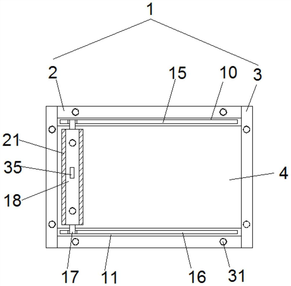
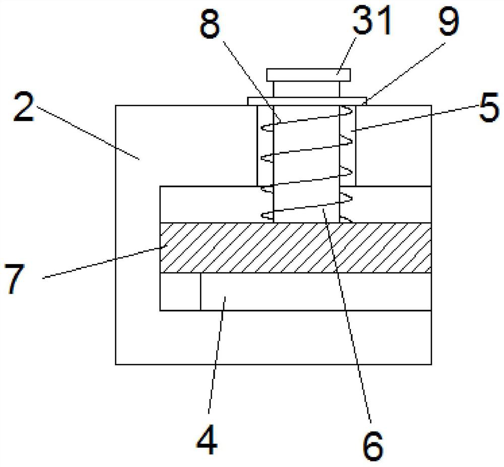
[0026] see Figure 1-8According to an embodiment of the present invention, an ironing system for garment processing includes a tensioning frame 1, and the tensioning frame 1 includes a horizontal tensioning frame 2 and a vertical tensioning frame 3, and the horizontal tensioning frame 2 is fixed One side of the horizontal tension frame 2 and one side of the vertical tension frame 3 are respectively provided with a fixing groove 1 and a fixing groove 2 between the vertical tension frames 3, and the tension frame 1 is internally fixed Clothing 4 is provided, and the clothing 4 respectively passes through the first fixing groove and the second fixing groove and extends into the first fixing groove and the second fixing groove, the first fixing groove and the second fixing groove The top of the fixed groove two is provided with a through hole 5, and the inside of the through hole 5 is provided with a movable rod 6, and one end of the movable rod 6 passes through the fixed groove o...
Embodiment 2
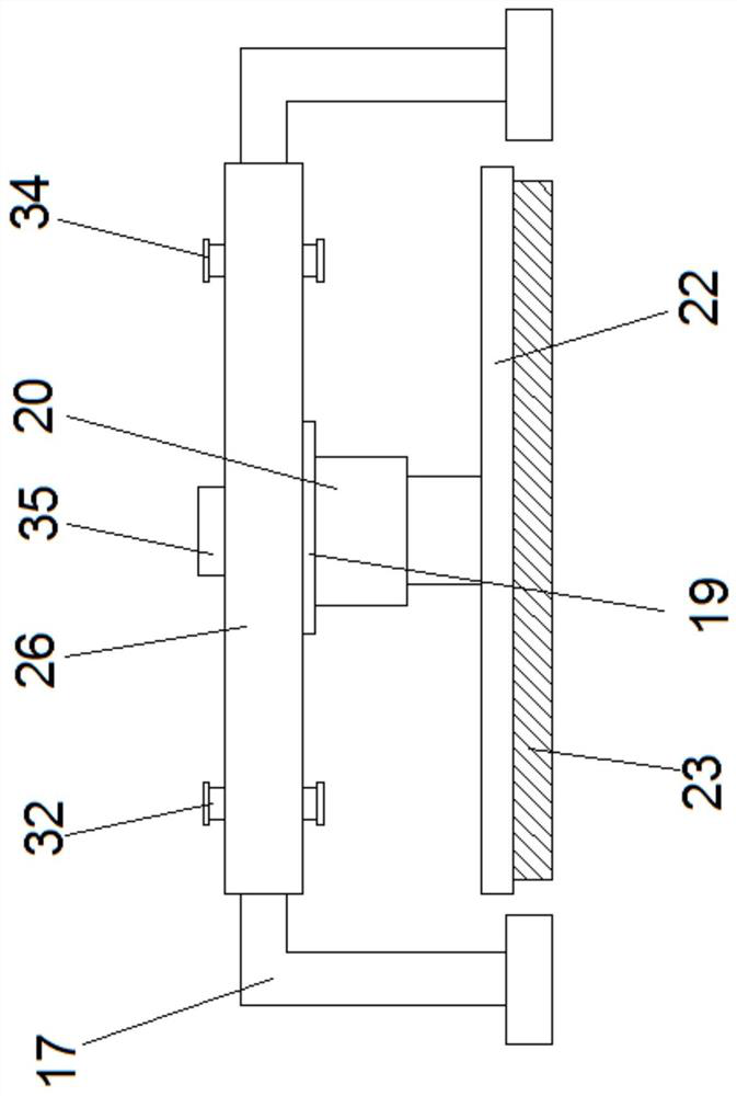
[0029] see Figure 1-8 , for the movable rod 6 , the end of the movable rod 6 away from the pressure plate 7 passes through the limiting baffle 9 and extends to the outside of the limiting baffle 9 to be fixedly connected with the adjustment block 31 . It is characterized in that threaded holes are opened on both sides of the adjusting sleeve 18 , and a screw 32 is threaded inside the threaded holes. For example, one end of the screw rod 32 is fixedly connected to the limit block 33 , and an adjustment knob 34 is provided at the end of the screw rod 32 away from the limit block 33 .
[0030] The beneficial effect of the above solution of the present invention is that the manual adjustment operation is facilitated by providing the adjustment block 31 and the adjustment knob 34 .
Embodiment 3
[0032] see Figure 1-8 , for the limit block 33, the side of the limit block 33 close to the U-shaped support frame 17 is provided with an anti-skid wear-resistant pad. As for the clamping plate 25 , a protective cushion is provided on the side of the clamping plate 25 close to the ironing machine 23 . As for the sliding rod 13, both ends of the sliding rod 13 are respectively fixedly connected to the inner wall of the adjustment cavity 11 through fixing blocks. As for the screw rod 12 , the end of the screw rod 12 away from the motor 14 passes through the bearing and extends into the bearing, and the bearing is fixed inside the adjustment chamber one 10 . As for the adjustment cavity one 10, a limiting track is provided inside the adjusting cavity one 10, and the slider one is slidably connected with the limiting track. For the U-shaped support frame 17 , a switch button 35 is mounted on the top of the U-shaped support frame 17 , and the switch button 35 is electrically con...
PUM
 Abstract
Description
Claims
Application Information
 - R&D
- Intellectual Property
- Life Sciences
- Materials
- Tech Scout
- Unparalleled Data Quality
- Higher Quality Content
- 60% Fewer Hallucinations
Browse by: Latest US Patents, China's latest patents, Technical Efficacy Thesaurus, Application Domain, Technology Topic, Popular Technical Reports.
© 2025 PatSnap. All rights reserved.Legal|Privacy policy|Modern Slavery Act Transparency Statement|Sitemap|About US| Contact US: help@patsnap.com