Winding wire insulating layer ring cutting device and ring cutting system applying same

A winding wire and insulation layer technology, applied in the field of winding wire quality inspection, can solve problems such as low efficiency, hidden dangers, and inability to form a closed loop, and achieve the effects of convenient and intuitive adjustment of load force, improvement of work efficiency, and reliable and convenient operation

Active Publication Date: 2021-07-16
TONGLING JINGDA SPECIAL MAGNET WIRE CO LTD
View PDF7 Cites 0 Cited by
  • Summary
  • Abstract
  • Description
  • Claims
  • Application Information

AI Technical Summary

Problems solved by technology

At present, the traditional ring cutting method is mainly manual cutting, that is, the operator holds a thin blade around the winding flat wire to cut the insulation layer, which is not only inefficient and time-consuming, but also has the following problems: First, the cutting direction Can not guarantee
When the thin blade circles the flat wire, it is often unable to form a perfect closed loop due to the vibration of the wire body or manual cutting errors.
Second, the cutting depth cannot be guaranteed, resulting in scratches on the surface of the conductor with different depths, which greatly affects the accuracy of later experimental data
Third, the thin blades are matched with thin flat wires, and it is easy to scratch your hands if you are not careful during operation, which poses a great safety hazard
Obviously, the above-mentioned manual circumcision method can no longer meet the high-quality and high-precision detection requirements of copper flat wires in the current high-speed development of industrial technology, and it needs to be solved urgently.

Method used


Image

  • Winding wire insulating layer ring cutting device and ring cutting system applying same
  • Winding wire insulating layer ring cutting device and ring cutting system applying same
  • Winding wire insulating layer ring cutting device and ring cutting system applying same

Examples


Embodiment Construction

[0045] For ease of understanding, combined here Figure 1-9 , the concrete structure and working mode of the present invention are further described as follows:

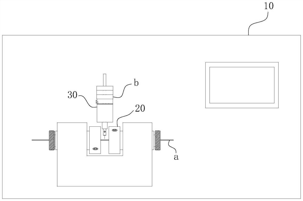
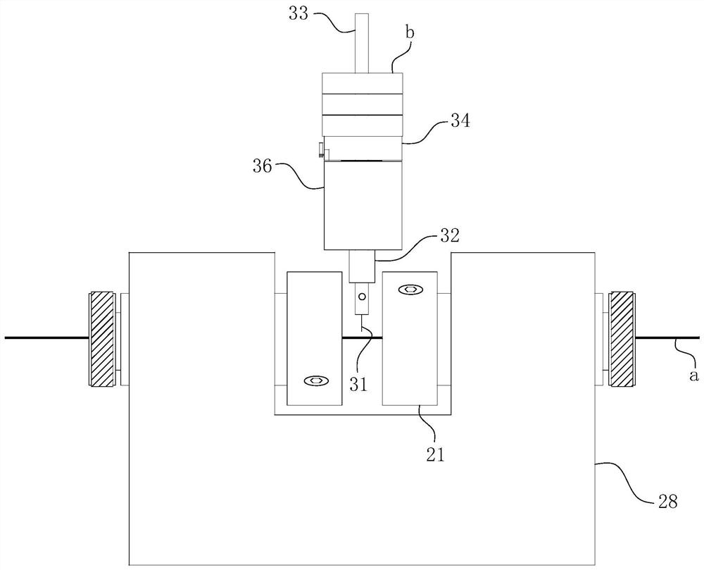
[0046] The specific structure of the present invention is as Figure 1-9 As shown, its main structure includes a frame 10 and a locking assembly 20 and a ring cutting assembly 30 located on the frame 10; the installation positions of the locking assembly 20 and the ring cutting assembly 30 refer to figure 1 and image 3 shown. in:

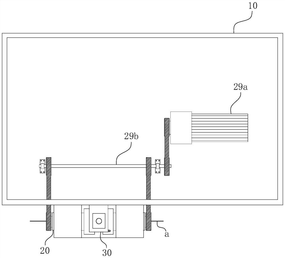
[0047] The locking assembly 20 includes a "U"-shaped trough-shaped workbench 28 fixed on the frame 10 , and two groups of claws are coaxially and oppositely arranged on the two sides of the workbench 28 . when working, such as Figure 1-2 As shown, the winding wire a is straightened and passed through two sets of claws, and then clamped and fixed by two sets of claws. The power starts from the power motor 29a with the driving wheel, passes through the transition rod 29b with the dri...


PUM


Abstract

The invention belongs to the technical field of winding wire quality detection, and particularly relates to a winding wire insulating layer ring cutting device and a ring cutting system applying the same. The ring cutting device comprises a rack, a locking assembly and a ring cutting assembly are arranged on the rack, the locking assembly comprises two sets of clamping jaws, and the two sets of clamping jaws are coaxial so that a winding wire can penetrate in the axial direction of the clamping jaws and be clamped by the clamping jaws; the two sets of clamping jaws are rotationally assembled on the rack; the ring cutting assembly comprises a ring cutting knife, and a cutting edge of the ring cutting knife points to a section of winding wire between the two sets of clamping jaws; and the ring cutting assembly further comprises an elastic pressurizing part which is used for applying loading force towards the winding wire direction to the ring cutting knife so as to cut through an insulating layer. According to the ring cutting device, the working efficiency of ring cutting operation of the winding wire insulating layer can be improved, and meanwhile the quality of finished products obtained after ring cutting can also be effectively guaranteed. The ring cutting system further comprises a current detection device, so that the automation degree of the whole ring cutting process and the accuracy of later detection are further improved.

Description

technical field [0001] The invention belongs to the technical field of winding wire quality detection, and in particular relates to a winding wire insulation layer ring cutting device and a ring cutting system using the device. Background technique [0002] With the rapid development of high-end electric vehicles, high-speed trains, ships, aerospace, heavy-duty equipment such as high-power high-speed machine tools, heavy-duty engineering equipment and other fields, high-performance motors have proposed large drive torque, high current density, and high power. New requirements for miniaturization and miniaturization. The high-performance, miniaturized and lightweight motor technology represented by the flat wire motor has higher efficiency than the traditional permanent magnet synchronous motor, higher power in the same volume, extremely high slot fill rate, and smaller copper loss, which is more suitable for It has broad prospects for application in high-tech fields such as...

Claims


Application Information

Patent Timeline
IPC IPC(8): B26D3/00B26D7/26G01N1/04G01R19/00
CPCB26D3/00B26D7/2614G01N1/04G01R19/0084
Inventor 彭春斌苏保信赵俊周超袁亚亚吕青王清华钟学成
Owner TONGLING JINGDA SPECIAL MAGNET WIRE CO LTD
Why Eureka
Try Eureka