Yarn suction device, full-automatic yarn twisting instrument and working method of twisting instrument

A fully automatic, yarn technology, used in measuring devices, instruments, scientific instruments, etc., can solve the problems of yarn winding and knotting, and achieve the effect of improving efficiency, solving yarn winding and knotting, and improving yarn arrangement efficiency.

Pending Publication Date: 2021-07-13
常州市智睿源信息科技有限公司 +1
View PDF15 Cites 0 Cited by
  • Summary
  • Abstract
  • Description
  • Claims
  • Application Information

AI Technical Summary

Problems solved by technology

[0004] The purpose of the present invention is to provide a yarn suction device, a fully automatic yarn twist meter and a working method of the twist meter, so as to solve the problem that the yarn is easily entangled and knotted when the fully automatic yarn twist meter is arranged.

Method used


Image

  • Yarn suction device, full-automatic yarn twisting instrument and working method of twisting instrument
  • Yarn suction device, full-automatic yarn twisting instrument and working method of twisting instrument
  • Yarn suction device, full-automatic yarn twisting instrument and working method of twisting instrument

Examples


Embodiment 1

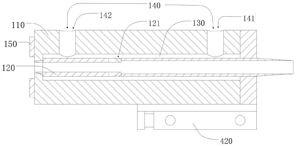
[0031] Such as figure 1 As shown, the present invention provides a yarn suction device which may include: gun body 110; yarn suction tube 120, which is arranged inside gun body 110 and runs through both ends of gun body 110; gas channel 130, which is opened inside gun body 110 and is located Periphery of yarn bobbin 120; air vent 121, which communicates gas channel 130 with yarn suction tube 120, and the inclination direction of air vent 121 faces the yarn output direction of yarn suction tube 120; and suction air inlet 140, opened on gun body 110 And communicate with the gas channel 130; after any suction air inlet 140 enters the air, the gas enters the yarn suction tube 120 through the gas channel 130 through the air port 121 and sprays toward the yarn output direction, so that the yarn suction tube located at the rear side of the air port 121 Negative pressure is generated in the space of 120 to suck the yarn from the front end of the yarn suction tube 120.

[0032] In thi...

Embodiment 2

[0036] On the basis of Embodiment 1, in this embodiment, the yarn suction device may only include one suction air inlet 140, and the air source 500 may pass a large flow of gas or a small flow of gas to the suction air inlet 140. When a large flow of gas is used, a negative pressure is generated in the space of the yarn suction tube 120 at the rear side of the vent 121 to discharge the yarn; Negative pressure for yarn straightening.

Embodiment 3

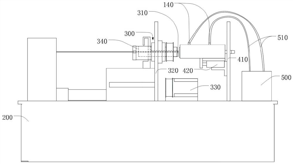
[0038] Such as figure 2 As shown, on the basis of the above-mentioned embodiments, the present invention also provides a fully automatic yarn twist meter, comprising: a rotary clamping mechanism 300, the tail end of which is provided with a yarn outlet 310 for yarn discharge; the above-mentioned yarn suction device , after docking with the rotary yarn clamping mechanism 300, it sucks and discharges the yarn from the yarn outlet 310 for yarn discharge by generating negative pressure; in this embodiment, the base 200 is provided with first brackets 410 with appropriate spacing and the second bracket 320; the yarn suction device is fixed on the first bracket 410 by one end of the push-pull device 420, and the yarn suction tube 120 passes through the first bracket 410; the rotary clamping mechanism 300 is arranged on the second bracket 320 and the yarn outlet 310 for yarn discharge is aligned with the yarn suction tube 120.

[0039] Further, the rotary clamping mechanism 300 inc...


PUM


Abstract

The invention belongs to the technical field of textile measuring instruments, and particularly relates to a yarn suction device, a full-automatic yarn twisting instrument and a working method of a twisting instrument. The yarn suction device comprises a gun body; a yarn suction pipe arranged in the gun body and penetrating through two ends of the gun body; a gas channel formed in the gun body and located on the periphery of the yarn suction pipe; an air inlet formed in the yarn suction pipe and inclining towards the right end of the yarn suction pipe; a small-suction air inlet hole formed in the gun body, communicated with the air channel and positioned on the left side of the air inlet; and a large-suction-force air inlet hole formed in the gun body, communicating with the air channel and located on the right side of the air inlet. According to the invention, the yarn arrangement mode that negative pressure is formed in the gun body to suck out yarn is adopted, and the yarn is pneumatically conveyed in the yarn suction pipe and is directly discharged out of the yarn suction device.

Description

technical field [0001] The invention belongs to the technical field of textile measuring instruments, and in particular relates to a yarn suction device, an automatic yarn twist meter and a working method of the twist meter. Background technique [0002] In the field of textiles, twisting is the process of twisting multiple strands of fine yarns in the axial direction and embracing each other to form thick yarns. Each twist of a multi-ply fine yarn is called a twist, and the twist is the number of twists per unit length of the yarn. The twist of the yarn will have a greater impact on the performance of the yarn and the appearance of the textile. Therefore, it is necessary to measure the twist of the yarn in production. [0003] The automatic yarn twist meter mostly uses the untwisting and twisting method to measure the twist. Every time the twist is measured, a section of yarn that has been untwisted needs to be discharged with a yarn discharge device. At present, the yarn ...

Claims


Application Information

Patent Timeline
IPC IPC(8): G01N33/36
CPCG01N33/365Y02W30/66
Inventor 孙伟平洪国权吴清斌
Owner 常州市智睿源信息科技有限公司
Why Eureka
Try Eureka