Cryoelectron microscope sample transfer system and method and electronic equipment

A cryo-electron microscope and sample transfer technology, applied in the field of scanning electron microscope, can solve the problems of difficult collision instruments, cryo-electron microscope sample structure, property change, unstable drop of the transfer table, etc., to achieve a reliable transfer environment, overcome instability and fall The effect of the structure that prevents the sample from heating up and collides with the instrument with difficulty in docking

Active Publication Date: 2021-07-13
INST OF GEOLOGY & GEOPHYSICS CHINESE ACAD OF SCI
View PDF6 Cites 1 Cited by
  • Summary
  • Abstract
  • Description
  • Claims
  • Application Information

AI Technical Summary

Problems solved by technology

[0003] In order to solve the above problems, that is, in order to solve the problem that the structure and properties of the cryo-electron microscope sample change during the transfer process, and at the same time overcome the problems of the transfer table in the prior art that are unstable and fall during the transfer process, and the docking is difficult and collides with the instrument, the present invention provides a Cryo-electron microscope sample transfer system, method, electronic equipment

Method used


Image

  • Cryoelectron microscope sample transfer system and method and electronic equipment
  • Cryoelectron microscope sample transfer system and method and electronic equipment
  • Cryoelectron microscope sample transfer system and method and electronic equipment

Examples


Embodiment Construction

[0055] In order to make the embodiments, technical solutions and advantages of the present invention more obvious, the technical solutions of the present invention will be clearly and completely described below in conjunction with the accompanying drawings. Obviously, the described embodiments are part of the embodiments of the present invention, not all of them. Example. Those skilled in the art should understand that these embodiments are only used to explain the technical principles of the present invention, and are not intended to limit the protection scope of the present invention.

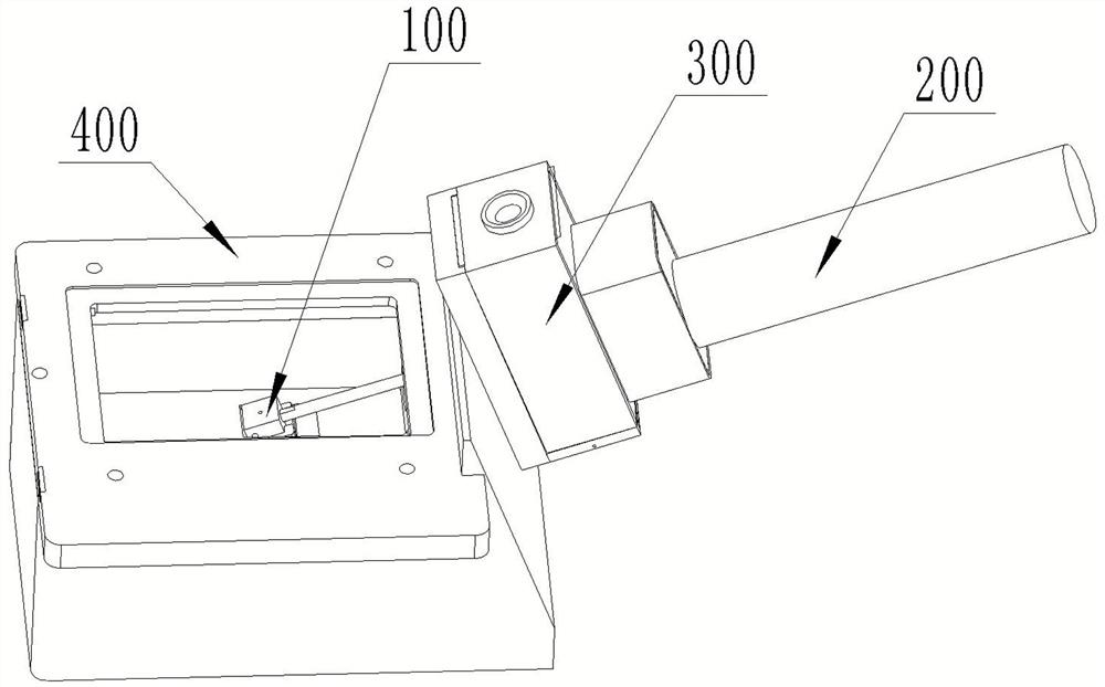
[0056] The first aspect of the present invention provides a cryo-electron microscope sample transfer system, which is used to transfer the prepared cryo-electron microscope sample from the chamber of the sample preparation device, wherein the inner bottom wall of the chamber is provided with a The installation slot for sample transfer. The system includes a master control center, a sample fix...


PUM


Abstract

The invention belongs to the technical field of scanning electron microscopes, particularly relates to a cryoelectron microscope sample transfer system and method and electronic equipment, and aims to solve the problem that a cryoelectron microscope sample changes in the transfer process. The system comprises a master control center, a transfer table base, a transfer device, a transmission rod, a moving device, a rotating device and a vacuum docking mechanism. The moving device comprises a first power device, a first transmission assembly, a transmission lead screw, a transfer rod sliding rail, a moving sliding block and a limiting sliding block. The rotating device comprises a second power device and a second transmission assembly; a moving assembly composed of a moving sliding block, a limiting sliding block and a transmission rod moves to the transmission rod to be in butt joint with the transfer device, and the limiting sliding block and a second transmission assembly are locked; a rotating assembly composed of a transmission rod, a limiting sliding block and a second transmission assembly rotates to the transmission rod and is locked with the transfer device; the transfer device and the moving assembly move to the vacuum docking mechanism; the structure and the property of the sample are effectively prevented from being changed in the transfer process.

Description

technical field [0001] The invention belongs to the technical field of scanning electron microscopes, and in particular relates to a cryo-electron microscope sample transfer system, method and electronic equipment. Background technique [0002] The sample room of the conventional scanning electron microscope is a high vacuum environment, which requires the observation sample to be dry and non-volatile. However, many samples contain water, oil or are volatile, so they cannot meet the conditions of the conventional electron microscope. At the same time, the loss of water and oil will also cause sample structure, The nature changes and the test data is distorted. The cryo-scanning electron microscope developed in recent years makes it possible to observe natural gas hydrates, oil-bearing rocks, biological cells, suspensions, hydrogels and other water-containing and oil-containing samples that cannot be observed by conventional electron microscopes with the help of ultra-low tem...

Claims


Application Information

Patent Timeline
IPC IPC(8): G01N23/2204G01N23/2251H01J37/28
CPCG01N23/2204G01N23/2251H01J37/28H01J2237/204
Inventor 杜忠明杨继进董文杰
Owner INST OF GEOLOGY & GEOPHYSICS CHINESE ACAD OF SCI
Why Eureka
Try Eureka