
Movable tidal generator

A mobile generator technology, applied in hydroelectric power generation, ocean energy power generation, engine components, etc., to achieve the effects of convenient and safe installation, low maintenance costs, and reduced manufacturing costs

Pending Publication Date: 2021-07-13
简国良
View PDF7 Cites 0 Cited by
  • Summary
  • Abstract
  • Description
  • Claims
  • Application Information

AI Technical Summary

Problems solved by technology

However, since the fixed platform is fixed at a certain position on the sea level by setting anchor chains on the seabed, the above-mentioned problems still exist.

Method used


Image

  • Movable tidal generator
  • Movable tidal generator
  • Movable tidal generator

Examples


Embodiment 1

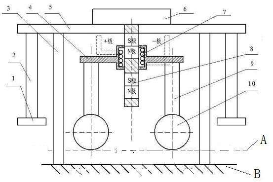
[0032] Such as figure 1As shown, the mobile tidal generator) consists of a generating coil base floating body 10, a generating coil base 4, a generating coil 7, a magnetic column 8, an equipment protection floating body 1, a magnet base 5, a load-bearing pillar 3, and a pressurized water storehouse 6. The magnet The seat 5 is downwardly connected with the equipment protection floating body 1 through the protection floating body connector 2, and the equipment protection floating body 1 is set to two or more, which are symmetrical or uniformly distributed in the circumferential direction; the magnetic column 8 is arranged on the magnet seat 5, and in this embodiment The magnetic column 8 is arranged in the middle position of the magnet seat 5, and the magnetic column 8 is arranged along the axial direction of the column to form S poles and N poles alternately spaced apart. 5, the function of the pressurized water chamber 6 is that it and the whole equipment self-weight offset th...

Embodiment 2

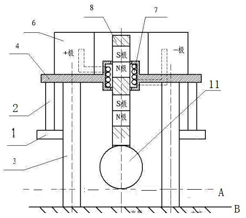
[0036] The tidal generator of the present invention can be transformed into figure 2 The structure shown: Compared with the embodiment, the magnet base 5 is canceled, the magnetic column floating body 11 is directly arranged at the bottom of the magnetic column 8, the pressurized water chamber 6 is directly arranged on the upper part of the generator coil base 4, and the load-bearing pillar 3 is fixed on the generator coil base 4 Above, the equipment protection floating body 1 is fixed on the generator coil base 4 and located on the periphery of the load-bearing pillar 3 through the protection floating body connector. At this time, the floating device for keeping the relative movement between the generating coil 7 and the magnetic column 8 becomes the magnetic column floating body 11 instead of the generating coil seat floating body 10 in the first embodiment.

Embodiment 3

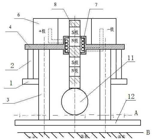
[0038] Such as image 3 As shown, the main difference between the mobile tidal generator of the present invention and the second embodiment is that the load-bearing pillar 3 does not touch the seabed B, but is fixed on the suspension platform 12, and the suspension platform 12 is located between the seabed B and the sea level A.

[0039] The ocean tidal power generation of the invention is not restricted by time and weather, can generate electricity all day long, and has low investment and maintenance costs. The rapid rise of the river water level during the flood discharge of the dam can also use mobile tidal generators in the river for secondary power generation. It has the following characteristics.

[0040] 1. Place the load-bearing pillar 3 on the seabed or on the suspension platform with the weight of the mobile tidal generator itself, and the seabed or the suspension platform bears the weight of the mobile tidal generator itself.

[0041] 2. The electromagnetic reacti...


PUM


Abstract

The invention discloses a movable tidal generator which comprises a bearing support, a magnetic column, a power generation coil matched with the magnetic column and a water pressing bin. The power generation coil is arranged on a power generation coil base, a through hole for the magnetic column to penetrate through is formed in the power generation coil base, the magnetic column penetrates through the through hole to form a sleeved structure capable of moving relatively with the power generation coil and the power generation coil base, and a floating device for maintaining relative movement through fluctuation buoyancy is arranged between the magnetic column and the power generation coil. The movable tidal generator is characterized in that the magnetic column and the power generation coil are both located above the sea level, and an equipment protection floating body is arranged on the periphery of the bearing support. Power generation equipment of the movable tidal generator completely floats above the sea level, the power generation equipment is prevented from being directly corroded by seawater, maintenance, replacement and installation operation under water is avoided as much as possible, and the movable tidal generator has the advantages of being simple in structure, easy to machine, low in construction difficulty, low in maintenance cost, movable, high in economic benefit, environmentally friendly, capable of generating power all day long and the like.

Description

technical field [0001] The invention relates to the technical field of power generation, in particular to a tidal generator. Background technique [0002] The clean energy that nature can provide: solar power generation is limited by weather, sunshine time and region; wind power generation is limited by weather and region; hydropower generation is limited by weather, reservoir capacity, large investment and huge engineering. Tidal phenomenon refers to the periodic movement of seawater under the action of celestial tidal force. It is customary to call the vertical fluctuation of sea surface as tide, which is commonly known as wave. Tidal is a natural phenomenon in coastal areas. Tidal energy is like Like solar energy, it contains huge energy, which is energy-saving and environmentally friendly, and it is inexhaustible and inexhaustible. At present, humans have used tides to generate electricity. Ocean tidal power generation is also a clean energy source provided by nature. O...

Claims


Application Information

Patent Timeline
Patent Type & Authority Applications(China)
IPC IPC(8): F03B13/26F03B13/00F03B11/02F03B11/00
CPCF03B13/26F03B13/00F03B11/02F03B11/00Y02E10/20Y02E10/30
Inventor 简国良
Owner 简国良
Learn More